XS650 Clutch Worm Actuator experiment & tidbits

thats a better angle and improved line which presumably reduces the steel cable holder wobbling about .

Why not do away with the cable guide Elbow altogether and drill and tap the crankcase cover for a short screw-in type cable guide adjuster!:thumbsup:

That way you eliminate any potential cable tension or friction losses

I would use a standard clutch lever adjustable cable guide
 

Attachments

  • 08-0067.jpg
    08-0067.jpg
    4.9 KB · Views: 506
Last edited:
Thanx, gggGary, scabber, peanut. I'll definitely put that E-Z pull cable on the experiment list. I can feel significant friction in those elbows by just sliding them up/down on the cable inner. My old cable from 39 years ago actually 'sawed' through the inside of the elbow...
 
Disassembled, and examined the clutch pushrod. Slight dimpling from the ball bearings is now starting to appear on the ends. The dimpling at the clutchpack end is centered, but the shouldered smaller-diameter worm end looks odd, multiple dimples.

Decided to revisit the dimpling modification.

Pic #1 - The clutchpack end of the pushrod needs to run concentric, so dimpled it.

Pic #2 - Needed to see if the worm actuator is concentric with the pushrod, because if not, forcing the pushrod to center on the worm could lead to pushrod resistance, and wear on the seal and bushing. The bushing and seal were recently replaced, and hold the pushrod in position quite rigidly. So, made a marking screw that would show worm/pushrod alignment. Running the screw through the worm adjuster hole, against the pushrod, produced a ring that I could check for eccentricity. Sure 'nuff, the worm and pushrod are misaligned about .007"-.008". But, in which direction, I don't know. Need to come up with a contrivance to figure this out, and how to do the centering, if necessary. This offset will be about .006" at the bushing/seal, and will cause considerable rubbing and wear there.

Pic #3 - So, decided to dimple the outboard end of the pushrod. It needs to freely spin, centered, and this dimpling will reduce the chance that random dimples caused by a wandering ball will cause any runout.

Pic #4 - Resurfaced the adjuster screw tip flat/square. The ball will seek its own center and not induce any sideload on the pushrod. Eventually, it'll dimple, but it will do it naturally, where it wants to dimple. In operation, the adjuster screw doesn't rotate enough to induce sideloads. 20°-30° of worm rotation with a .007"-.008" offset produces only .002"-.003" movement at the pushrod bushing, easily tolerated by the pushrod bushing/seal. By removing the 'tip-over' torque with the modified worm arm, the worm will hopefully remain well-centered, and not add much to this eccentricity.
 

Attachments

  • WormR01.jpg
    WormR01.jpg
    91.8 KB · Views: 333
  • WormR02.jpg
    WormR02.jpg
    118.5 KB · Views: 379
  • WormR03.jpg
    WormR03.jpg
    79 KB · Views: 344
  • WormR04.jpg
    WormR04.jpg
    181.4 KB · Views: 342
Summary of the mods to date:

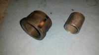
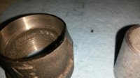
All tests were done with a 16 year-old cable, configurations #2, #3, and #4 using an old worm working in a worn/cracked worm housing.

Actuator was adjusted to 1/8 turn from fully seated. Excluding slack, this gives 0.60" of potential cable travel.

Lever pull tests were done at the lever end, 6" from the lever pivot, with force measurement taken at mid-travel. The clutch lever pivot to cable end distance is 1", giving a 6:1 leverage to the cable from this measurement point.

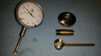
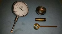
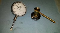
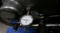
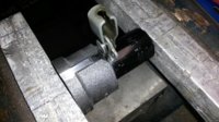
Actuator plunge measurements were taken with a depth guage on the side cover housing and worm outer edge.

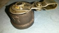
Configuration #1 - Stock XS1 worm, 1.3" clevis hole distance
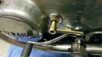
Configuration #2 - Arm bent down 0.4", 1.3" clevis hole distance
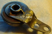
Configuration #3 - Arm bent down 0.5", 1.7" clevis hole distance
Configuration #4 - Same as configuration #3, modified cable/elbow entry angle

#1: Pull-test = 26 lbs, Actuator travel = 0.065", Cable tension = 156 lbs
#2: Pull-test = 18 lbs, Actuator travel = 0.070", Cable tension = 108 lbs
#3: Pull-test = 15 lbs, Actuator travel = 0.055", Cable tension = 90 lbs
#4: Pull-test = 14 lbs, Actuator travel = 0.057", Cable tension = 84 lbs

The clutch worm actually has a 32mm pitch, moving 1.26" per turn, about .0035" (0.09mm) per degree of rotation.
The force required to compress the clutch pushrod to mid-travel was 370 lbs.
This would require (in an ideal frictionless environment) 77 inch-lbs of torque on the clutch worm.
The actual torque required to rotate just the clutch worm, at mid-travel, measured at 86 inch-lbs, about 7 ft-lbs.
This is only about 12% over frictionless, so the clutch worm intrinsic friction is quite low.

With an ideal frictionless clutch cable:
86 inch-lbs torque, on a 1.3" lever arm, would require a cable tension of 66 lbs, 11 lbs at clutch lever end.
86 inch-lbs torque, on a 1.7" lever arm, would require a cable tension of 51 lbs, 8.5 lbs at clutch lever end.

The excessive cable tension is the 'overhead' of the contraption, and is:

#1: 156 lbs - 66 lbs = 90 lbs overhead, 58% of total force
#2: 108 lbs - 66 lbs = 42 lbs overhead, 39% of total force
#3: 90 lbs - 51 lbs = 39 lbs overhead, 43% of total force
#4: 84 lbs - 51 lbs = 33 lbs overhead, 39% of total force

It appears that cable friction accounts for about 39-43% of total force. I'm sure this also contributes to reduced travel.

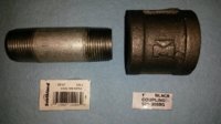
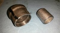
Future tests are planned using the second modified worm (with the welded arm), the other new/unused clutch cables, an EZ-pull cable, and the new, black, harder composition worm body available from MikesXS.

Right now, I'm very pleased with this new clutch action. The clutch starts to engage when the lever is let out about 2/3rds from the grip, and is a softer engagement. I can work it with just one finger, but that's just bragging and has no real meaning...
 
Last edited:
Been riding around with this new clutch worm thing for awhile (configuration #4). It's different. Much easier to work, and has a softer engagement. Having to learn to ride this thing all over again. The hot/expansion issue is still there. In town, hot and low speeds, you can feel the extra 1/2" of slack. Clutch engagement (when hot) occurs at about lever half travel. But, 'standing-still neutral' is easy to hit, reminds me of easy to hit neutrals of brand-new Hondas of the day. It's never done this before.

Aside from the rebent worm arm, the only real change here is going from the quicker 1.3" XS1B arm to a longer 1.7" arm. The replaced XS1B worm is in better shape, the push rod had already had the dimpling mod done long ago, clutch cable and lever are unchanged, and I'm using the same adjustments. By all rights, the clutch should be worse, dragging with impossible-to-find neutral.

Interestingly, the 'hot' cable slack goes away at highway speed. Takes some getting used to.

Ordered the MikesXS 'new' clutch worm assembly, and ordered the EZ-pull cable from M. Morris 650Central (a real fun guy to chat with, those California boys had all the fun back in the day). So, more experimentin' will be happening.

The 'depth guage' method I'm using is very awkward and difficult. Want to make a simple/lightweight dialguage adapter using an old adjuster cover. Thinking about attaching a 3/8" ID aluminum pipe with a lockscrew to a cover. Then, a lightweight dialguage could slide-in, with preset depth...
 
HF used to have a goose neck type holder with a vice grip on the end. I'm sure you could rig that up somehow for quick measurements on the worm side. I used it on the other side a few years back to check pressure plate movement .....

U2fQDFr.jpg
 
Last edited:
I'll have to do some digging through my notes. I know I wrote it all down somewhere, lol. I do recall being surprised how little the plate moved, a little under 2mm if I recall. Divide that amongst all the steel and fiber plates and you get very little separation between each one. I also took measurements with the factory 1/4 turn out from touching worm adjustment and my barely 1/8 turn out. That made a measurable difference as well.

Some other measurements I checked during this session were the height of the clutch pack from the cover mounting surface on the crankcase and the depth of the cover itself from its mounting surface to its inner side. Now, I think most of us agree that more pressure plate movement resulting in more plate separation is our goal but the amount of clearance in there is very limited. Get the clutch to expand a little too much and you may get this result .....

yofTGSu.jpg
 
Last edited:
Decided to make a guage holder to measure clutch worm travel.

Pic #1 - El-cheapo dial guage is conveniently lightweight and has a 3/8" shaft. Brass 1/4" NPT is used here. The tubing has a 3/8" ID. So, fitted a brass fitting into an old adjuster screw cover, slotted a nipple at one end, and made a collet nut with handle.

Pic #2 - View of the other side.

Pic #3 - Assemble the parts, and the guage holder is ready to go.
 

Attachments

  • WormGuage01.jpg
    WormGuage01.jpg
    134.8 KB · Views: 340
  • WormGuage02.jpg
    WormGuage02.jpg
    133 KB · Views: 301
  • WormGuage03.jpg
    WormGuage03.jpg
    141.3 KB · Views: 330
Pic #1 - The guage holder is popped into place

Pic #2 - The dial guage is fitted into place, setting the depth as needed. Then the collet is snugged.

Pic #3 - Ready to take a measurement.

The reading I got in this configuratiion #4 was 0.047", less than the reading I got using the caliper depth guage. So, all the previous readings are probably null and void. Still have the original unmolested XS1B clutch worm (configuration #1), so will re-fit it and take a reading. Then can re-run configuration #2, since the 1.3" hole is still there. Hopefully, they'll all be off by a consistent value, due to the way I was trying to hold the depth caliper.
 

Attachments

  • WormGuage07.jpg
    WormGuage07.jpg
    127.2 KB · Views: 355
  • WormGuage06.jpg
    WormGuage06.jpg
    112.5 KB · Views: 367
  • WormGuage05.jpg
    WormGuage05.jpg
    165.4 KB · Views: 387
thats an elegant and effective solution !:thumbsup:

If ever I'm in a plane crash in the desert I hope you're one of the passengers (flight of the pheonix):laugh:
 
Thanx, peanut! 'Flight of the Phoenix' (the original Jimmy Stewart version) is one of my favorites. Dad took me to see it when it first came out, mentioned he knew the stunt pilot who died in the crash during filming of that thing, so the landing scenes are not in the movie...
 
.047 is 3/64" the plunger most likely sticking and giving a false reading. It happens a lot especially when you need it the most. Moving the hole from 1.3 to 1.7 give slightly less pushrod travel The offset arm might cause the side cover to flex less finding neutral easier. My guess. You probably have the E-Z pull cable by now I'm pretty shure the stickout is longer than the stock cable. You can set the arm at optimum. Interested in your findings on mikes actuator better or not. Going to make the 1/2" offset like yours 2 holes 1.3" and 1.7" and go with what works the best. Keep up the good work.:thumbsup:
 
Thanx, scabber. I'm going to double-check that budget indicator. It was interesting to see the indicator needle move in sync with the clutch lever. Might even try riding with it and note the travel values at clutch engagement, disengagement, and hot-engine slack.

The EZ-pull cable and a new MikesXS clutch worm showed-up this evening, just as it started to sleet out here. So, my progress will slow down like molassis in winter. The MikesXS worm body is made from a very rigid self-lubricating plastic (polycarbonate?), and should be an interesting experiment.

It's encouraging that you'll be trying this. Working solo on just one model makes it difficult to confirm findings, anxious to hear your results...
 
For those of you who may want to try this 'rebent worm arm' trick, here's a crude method that should work.

You'll need to make a simple clamping jig that protects the worm and seal cup, and allows sufficient support to rework the arm.

Pic #1 - Started with plumbing pipe. A 3/4" nipple will be used to slide over and protect the worm. The 1" coupler will be modified to fit over the seal cup and clamp to the worm arm. This particular 1" coupler is black iron, not a good choice, but it's all I could get at the moment.

Pic #2 - Both pieces are cut and faced-off to a length of about 1.2" (anything 1" or over is fine). The inner pipe needs to be about .010"-.020" shorter, to account for the thickness of the seal cup.

Pic #3 - The ID of the outer pipe needs to be about 1.475", to surround and protect the seal cup. The ID of the inner pipe needs to be around 0.800", to slide over the worm.

Pic #4 - An edge of the outer pipe needs to be relieved to give clearance to the new bend angle of the worm arm. This will be the working edge. A mark of some type needs to be made at about 0.350" from the working edge, to serve as a guide to indicate the final bend of the worm arm. Here, a notch is made, and a steel rule can fit into the notch and used as the guide.
 

Attachments

  • WormToolA01.jpg
    WormToolA01.jpg
    151.1 KB · Views: 313
  • WormToolA02.jpg
    WormToolA02.jpg
    136.4 KB · Views: 341
  • WormToolA03.jpg
    WormToolA03.jpg
    149.3 KB · Views: 334
  • WormToolA04.jpg
    WormToolA04.jpg
    119 KB · Views: 340
Pics #1 & #2 - Slide the smaller/inner pipe over the worm. Make sure that the rubber seal has been removed first.

Pic #3 - Slide the outer pipe over the seal cup, aligning the working edge under the worm arm.

Pic #4 - A 3/4" socket can be used on top of the assembly to complete the clamping process. Don't clamp against the worm extension (the splined protrusion with the 3 tack-welds). Orient the socket so it sits flat on top of the worm arm, not on the welds. Use whatever socket size/type gives the best/flattest support and clamping force.

Clamp down tightly, but not so tight that things distort. Now, the worm arm is held rigidly and isolated from the rest of the worm.

If I had another long-arm worm, I could show pics of the next steps. Recently received a new MikesXS worm, will use this tool on it after getting some pre-modify measurements.

The first step would be to straighten-out the arm's outer bend, easily done with large pliers or vicegrip. Then, the entire arm is bent down against the working edge of the outer pipe, using pliers and/or hammer/punch. A torch could be used if need be. Occasionally check that the vice is tight.

Once the arm is bent down about 45°, The outer bend needs to be made. Using the reference mark at 0.350", bend the second half to a straight vertical, with the bottom surface of the arm aligned even with the reference mark. The finishing touch is to have this outer part bent/twisted about 8°, to align with the new cable angle (pic #5). The bottom surface of the arm should be close to the same level as the bottom of the seal cup.
 

Attachments

  • WormToolB04.jpg
    WormToolB04.jpg
    172.3 KB · Views: 361
  • WormToolB03.jpg
    WormToolB03.jpg
    153.4 KB · Views: 369
  • WormToolB02.jpg
    WormToolB02.jpg
    84.3 KB · Views: 357
  • WormToolB01.jpg
    WormToolB01.jpg
    141.5 KB · Views: 332
  • WormToolB05.jpg
    WormToolB05.jpg
    184 KB · Views: 355
TwoMany---Great pix and write up. Any interest in selling a setup like that ??? tim
 
Back
Top