rephase rebuild strangeness

With the degree wheel dialed in for TDC on the left cylinder, you can only measure the valve movements on the left cylinder.

Set up a second pointer on the degree wheel for the right cylinder, then measure all the valve events for the right cylinder using the second pointer.

Without knowing the actual opening and closing events for both cylinders there is no way to know exactly what is going on.
 
Good tip mrriggs I will try just that
And yes, I have put the videos the wrong way round - the bluish one is inlet and the yellowy one is exhaust
 
Well since I haven't seen any dial indicators and no cam specs so the rest of this is guess work. Since the motor turns over and the valves are not hitting the pistons is good sign. Beg borrow or steal a compression gauge turn the motor over and see what it reads both sides. Lot of other things should be checked to assemble a motor properly I won't go into that at this point. This would help more than a vidio. A balloon fastend to hollowed out sparkplug should tell when the timing events start inflate deflate when the exhaust valve opens better than eyeballing the valve.
 
What is everyone using for a piston stop when you have a complete engine and just want to get the TDC mark accurate. Have used a dial gauge but it gets bent easily if not exactly in the right location, probably because the valve touches it or the angle to the piston is a little steep and it gets bent. When setup right it will work though. Also tried the bolt in a tapped out spark plug, but the bolt ends up being too big and contacts the valves. Possibly remove the rocker shafts and rockers, but that seems excessive.
Anyone have some easy solutions. Doing a PMA change and want to make sure my new marks are accurate.

The valves should be closed at Tdc if you have a grinder grind the bolt smaller diameter to clear.Clean it before you use it.
 
Last edited:
I saw a piston stop made from an old spark plug; bust the ceramic and remove it from the shell, cut off the negative electrode. Weld or braze a 3/16" nut to the top of the shell, then use a 3/16" bolt that's threaded its full length in that nut. Run the shell into the plug hole, run the bolt all the way in, turn the motor by hand and keep backing the bolt out. You'll quickly find the spot where it goes 'over center', back up a smidge and there's your TDC. If you put a second jam nut on the bolt, you can lock it into place easily.
 
Make, beg, steal or borrow a piston stop.

Attach a degree disk and pointer.

Rotate the crank until the piston comes up the bore and contacts the stop. Zero the degree disk.
Turn the crank backward through b.d.c. until it contacts the stop again and note the degrees.

Half this reading will be b.d.c. and adding 180 degrees will give you t.d.c.

Yes it may be a pain removing the rockers (could try backing the adjusters right out?) but once you have an accurate mark that's the issue sorted.
 
Here's what I'm using.

Cut off flange. I used a lathe but the same could be done with a bench grinder or file.
PistStop01.jpg


Cut off ground strap and smack out the porcelain.
PistStop02.jpg


The hole is already the right size but I cleaned it up with a drill anyway.
PistStop03.jpg


Thread with 10Mx1.25 tap.
PistStop04.jpg


I just happened to find this bolt in my stash that was the perfect length.
PistStop05.jpg


PistStop06.jpg


Unscrewing the valve adjusters has given me enough clearance to turn the motor over completely without the valves hitting the stop (YMMV). This allows me to leave the stop fully threaded into the head while finding TDC. That is quicker and more accurate than unscrewing it, rolling it past TDC, and screwing it back in again.
PistStop09.jpg


With the stop threaded in, turn the motor clockwise until it stops. Be gentle, you don't want to shove the stop through the top of the piston.
PistStop07.jpg


Then turn the motor counterclockwise until it stops.
PistStop08.jpg


Notice it stopped at 28.5 degrees both times. That means that the degree wheel is dialed in on TDC. The exact number doesn't matter, they just need to be the same as eachother. If you get different readings then move the pointer half of the difference of the two, then check it again.

Like I mentioned before, if you are doing a re-phased motor then you will need to move the stop to the other cylinder and do the same procedure with a second pointer.
 
Last edited:
Blimey, my head is starting to hum! This is all good stuff... I like the balloon idea and Max's method for finding bdc then calculating tdc. Also haven't done a comp test yet so will definitely do that. I'm thinking I could use a length of oversize wooden dowel, whittled to a taper and a snug fit in the plug hole as a piston stop. Then use that to find bdc. More investigation this evening.
 
SHAKEY someone came in with unrelated Question and trashed the thread.do the compression check that will tell you if the cam is in right since jerry heiden did the crank and cam he should give you what Information you need to install. IF you got no information with the crank and cam ask for it. you need the cam timing specs. Intake opening and cloesing events to degree the cam. here is an example intake opens 35 deg. btd intake closes 67 deg. atd exhaust. Compression on both cylinders will tell us if the cam and are in right. More information is needed give us all you got
 
Right, here's the latest: got an email back from Jerry and he said the following;
The new firing order is RH piston in TDC valves closed.
The location pin of the advance unit to the top.
270 degr .later the left piston in TDC valves closed.
If it is not like this , then I made a mistake!
In some cases people ask me to make it on a different way.
It is possible that I made this . during that week I made more cams
On a different way.
Then I have to make another cam for you.
Please check it.

I checked and it sure ain't like that. No access to a compression tester (or balloon!) this evening, but got handy with the degree wheel and separate pointers for left and right as per Mrriggs. Here's what I got...

With Left @ TDC (pointer No.1 = zero degrees)
Inlet Valve opens @ 38 BTDC; Fully open @ 105 ATDC; closes @ 120 ATDC
Exhaust Valve opens @ 105 ATDC; Fully open @ 120 BTDC; closes @ 38 ATDC
(this looks ok)

With Right @ TDC (pointer No.2 = zero degrees)
In opens @ 150 BTDC; Fully open @ 80 BTDC; closes @ 80 ATDC (!!!)
Ex opens @ 68 BTDC; Fully open @ 68 ATDC; closes @ 150 BTDC

Shining a torch through the right plug hole it looks like the inlet valve actually touches the piston at the top of its stroke - I think this is causing the 'jump' that I referred to in an earlier post. Thank **** I didn't try starting the engine in this state!

Finally I measured rotation from tdc on one side to tdc on the other:
With Left @ TDC, Right has come up to TDC 83 degrees before;
With Right @ TDC, L = TDC 94 degrees later.
Either way I can't see the numbers adding up to 277 - you'd have to add 180 (half a revolution) to get to 277, but wouldn't that relate to one of the pistons @ BDC ????:confused:

Upshot is I reckon I've got the wrong cam.
I'm also now wondering if the crank is correct? I'm gonna get all this info back to Jerry and see what he says. If it turns out to be incorrect either way then I trust it's a mix-up at Jerry's end and hopefully easily sorted. I'll report back in due course.
Thanks for all your thoughts so far guys:thumbsup:
 
Your numbers are kind of skewed but if I interpret it correctly the left intake is;

open 38 BTDC, center 105 ATDC, close 60 ABDC

and the right intake is;

open 30 BBDC, center 68 BTDC, close 68 ATDC

the difference between these is;

right open advanced 172, right center advanced 173, right close advanced 172

If these numbers are right then that means that the right side of your crank was retarded 83 degrees, and the right side of the cam was advanced 89 to 90 degrees. It sounds like he sold you the cam for a (righty) 270 re-phase instead of a (lefty) 277 re-phase. I'd be surprised if you didn't bend a valve or two on the right cylinder. Also check that you didn't crack the valve guides or collapse the top ring land.
 
Last edited:
Here's a homemade TDC stop I made a few years ago.. It's a little crude but gets the job done. It has a stop nut on it to lock in your depth and the threaded part that goes into the spark plug is slotted lengthwise (not shown in pic) so it is easier for air to escape the cylinder.

tdc.jpg
 
Good thing you couldnt get a comp tester, who knows what carnage that would have caused! At least your dealing with a gentleman and im sure that he's very embarased about it and keen to make amends. These things are sent to try us, and your getting there! :thumbsup:

Posted via Mobile
 
Good thing you couldnt get a comp tester, who knows what carnage that would have caused! At least your dealing with a gentleman and im sure that he's very embarased about it and keen to make amends. These things are sent to try us, and your getting there! :thumbsup:

Posted via Mobile

Indeed! Thanks for the moral support:)
 
Glad you found it before startup! This thread shows why it's always best to test something before actually firing it up. Good luck with the rework.
 
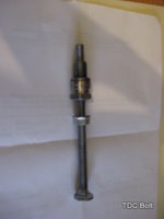
This is one i made some time ago, but found the 3/8" bolt contacts the valve.

Will try the remove valve adjuster trick, but am also thinking of reducing the diameter of the first 1/2 to 3/4" of bolt down to 1/4" and see if that allows enough room for no contact with the valves.

Wish i had a spare head to try this on so I could see the valves moving and bolt interference visually.

I had my marks all setup when doing the rebuild, so understand the procedure for getting TDC accurately, but have since added a PMA and having trouble with the 4 to 5 mm key and getting the new timing marks reset when the engine is all together. Hard to hold a small key and still get it filed down to fit the banshee rotor 5mm and stock crank keyway 4mm.

Oh the joys of modification and the endless pursuit of perfection.
 

Attachments

  • IMG_1525_bolt.JPG
    IMG_1525_bolt.JPG
    20.7 KB · Views: 86
Back
Top