TCI forensics NO WONDER!!! they are problems!!!

mouser

XS650 Addict
Messages
228
Reaction score
2
Points
18
Location
Sunshine Coast British Columbia
A recent post about TCI repair inspired me to dig out an old one and pry the lid off and have a look! I was shocked! I have a background in electronics I studied it in school and worked several years in the medical instrument field building heart monitors, defibrillators, and that sort of thing.
I removed the circuit board and dragged out a digital microscope to better examine it.
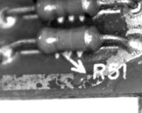
I didn't even to put my glasses on let alone turn on the scope to spot glaring irregularities. The board itself is of very low quality.
I spotted immediately many poor soldering connections. I would estimate a full 1/3 of the probably 100 connections would have failed inspection where I was employed. Most were cold joints, bubbles in the solder, from cooling too fast, not enough heat, or cooling by blowing on the joint to cool it.
The board itself after soldering was never cleaned to remove the residual resin and spatters of solder. It was coated by some sort of sealer over the dirt by spray. The edges of the board were never sealed. Any moisture and air was able to get under the varnish, react with the resin and corrode the conductors.
Actually I am surprised this thing actually ran my bike, which it did very well except whatever controls the auto advance. It started, ran perfectly, but no rpm...auto advance circuit....
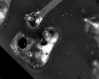
I looked at the main 6 wire connections on the board. The orange wire which would be a coil output and the green white goes to the pickup are both very poor connections...??? hmmmm:doh:
here are a few illustrations to check out if this interests you.
This is my main orange connection....
4.jpg

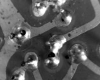
this is a favorite!!! 8 connections! ...all bad...and two "bridges"
7.jpg

this is what happens if you don't wash resin off....then let air or water at it...in this case through the porous unvarnished edges......:eek:

22.jpg

I find it rather disturbing when I explored Hitachi and find they make aircraft components!!!!!!!

Tomorrow I have a meeting with an electrical guru to discuss re engineering the whole unit.....He is intrigued at this point....and knows his business...
I'll keep you updated...

Today I will re solder the whole board and melt the bridges!!!

I am convinced I can correct this one..

To test this board I need to repeatedly connect and reconnect the unit. I want to better know which of the many faults is the one that actually caused the malfunction.. Is there any precautions I should observe when I do the switches to protect the units? I am afraid of ruining the good one I am using..
 
That's some horrible soldering work. I can't believe that made it to the line. Reminds me of my old Chrysler T&C. It had all kinds of freakish electrical problems that all stemmed from a badly soldered circuit board behind the speedometer. Once I fixed it, problem gone. I think it was made in China.
 
Old Honda's have what is called a multy relay. If your old honda is having wierd symptoms, you can be sure the multy relay is at fault. The last time our '94 Accord stopped running and gave a slew of confusing codes I pulled the board and just resoldered it. Ran like a top when I put it back in. This was the second board BTW. Years later I got a call from the kid who had bought the car while I was on vacation. I diagnosed the multy relay as the problem. His dad bought a new one and the car is still running well.

Rick-the-fix on the Yam650 list goes through and fxes bad TCI's. He is not an EE, just a hobbyist. He finds blown power transistors and bad solder joints.

I note the two pick-ups on the stator and figure one must be idle retard and the other full advance. What I can't figure is how the advance works between them. It seems that the retard timing pick-up can be a more powerful winding so it gives a stronger signal at low rpm with the weaker advance pick-up sending an increasingly stronger signal at higher rpm.

I'll be interested in what you can reverse engineer mouser.

Tom Graham
 
You have an unusually bad one that I doubt is representative of the whole run. Neither of mine have the solder problems. Yours has a more expensive board material, too. One of mine had solder problems on a couple of pads that were obviously due to years of vibration.

Conversely, you could attribute the fact that yours ever ran to the robustness of the design. Really :)

BTW, your friend will not have much luck with the board unless he can find data for the DIP. Also, if it were being made today, the only real reason to reverse engineer it, the new TCI board would be done from scratch, and be based around a single chip microcontroller, which would eliminate nearly all the parts. I could do it, but I have no reason to. Because it would be for free :)
 
I was thinking more on the line of rebuilding the unit exactly as it stands...with a quality board ...upgraded components where possible, and recycling the DIP from existing units.
How many xs's were built with these ignitors? Anyone have that info at their fingertips?? I wonder how many varieties of these boards were made, for what years, and in and for what countries??...I'm guessing there might be a way of sorting these things out!...
I'm working on it..........

My friends area of expertise is vintage electronics...this is right up his alley!!!!
 
xjwmx! exactly my point ! and a better way of expressing it....:thumbsup:

"Conversely, you could attribute the fact that yours ever ran to the robustness of the design. Really"

Properly manufactured or re manufactured these things should/and should have, worked forever..

THnx!
 
I would like to see and document photos members could provide me of the guts of these boards, front and back, dead or alive! and tell me what it came from. Model, year, anything that might help! I'm on a mission !!
 
You have an unusually bad one that I doubt is representative of the whole run. Neither of mine have the solder problems. Yours has a more expensive board material, too. One of mine had solder problems on a couple of pads that were obviously due to years of vibration.

Conversely, you could attribute the fact that yours ever ran to the robustness of the design. Really :)

BTW, your friend will not have much luck with the board unless he can find data for the DIP. Also, if it were being made today, the only real reason to reverse engineer it, the new TCI board would be done from scratch, and be based around a single chip microcontroller, which would eliminate nearly all the parts. I could do it, but I have no reason to. Because it would be for free :)

I don't care about money for my efforts. If I am successful and can fix this fault in an otherwise spectacular motorcycle ...I'll fix em all....at cost! I'm just trying to help!
:)

I bought my first in 1977 ....I have logged 100,000 miles + on them......I have never had to push one home yet! I love these bikes!
 
I still haven't even taken the time to explore what the phuque a Pamco is! They work well just as they are...just need a little luvin attention!....and at their age, especially so! Do it and they will outlive you!

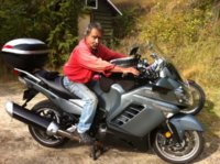
or buy one of these! I helped out a traveler yesterday with this bike! With a brake issue 1400 cc .....135 km/hr in first gear!...I gratefully declined his offer to take it for a boot around the block after I repaired it.........bled the brakes.....he is off to Alberta....

I'm happy with my xs! I'm an old fart!
photo.JPG
 
Last edited:
I note the two pick-ups on the stator and figure one must be idle retard and the other full advance. What I can't figure is how the advance works between them. It seems that the retard timing pick-up can be a more powerful winding so it gives a stronger signal at low rpm with the weaker advance pick-up sending an increasingly stronger signal at higher rpm.

I'll be interested in what you can reverse engineer mouser.

Tom Graham

I believe you are correct about one pickup being base timing and the other being total. I looked up the IC some time back. I couldn't find a spec sheet for it but found reference to it being a frequency-to-voltage converter. My suspicion it that it is used as an RPM switch. So the ignition fires off of the base timing pickup until you reach a certain RPM, then it switches over to the advanced pickup. It sounds crude (and is) but that is exactly how the TCI on my XS400 works.

I have wanted to probe one of these for some time but never had a running bike with a TCI. I would be happy to lend my time, and my oscilloscope, to the cause. Is there anyone in the Portland/Vancouver area with a TCI bike that would like to hang out at my place one Saturday?
 
BTW, your friend will not have much luck with the board unless he can find data for the DIP. Also, if it were being made today, the only real reason to reverse engineer it, the new TCI board would be done from scratch, and be based around a single chip microcontroller, which would eliminate nearly all the parts. I could do it, but I have no reason to. Because it would be for free :)

I have already designed a single-microcontroller digital ignition that would be a cinch to adapt for this application. It was designed for drag racing and has way more features than the modest XS will ever need but you could simply program in a basic advance curve and rev limiter and ignore everything else. Feel free to use it. It'd take you far less time to set it up than to reverse engineer the stock box. Plus, it is a more sophisticated design with digital advance control and a ramp-and-fire dwell strategy.

http://www.gofastforless.com/ignition/digital.htm
 
I believe you are correct about one pickup being base timing and the other being total. I looked up the IC some time back. I couldn't find a spec sheet for it but found reference to it being a frequency-to-voltage converter. My suspicion it that it is used as an RPM switch. So the ignition fires off of the base timing pickup until you reach a certain RPM, then it switches over to the advanced pickup. It sounds crude (and is) but that is exactly how the TCI on my XS400 works.

I have wanted to probe one of these for some time but never had a running bike with a TCI. I would be happy to lend my time, and my oscilloscope, to the cause. Is there anyone in the Portland/Vancouver area with a TCI bike that would like to hang out at my place one Saturday?

After much thought I think this is auto advance ignition was a bad idea! I think they would have been further ahead to set it up for a fully advanced ignition with a circuit and a "button" to retard the spark for cold starts.... I'm thinking back to the day when Harleys and Indians and many more...had a mechanical way of retarding the ignition for starting. The only time it was necessary to retard the spark was for the first cold start of the day....or they would kick you back...and to intentionally retard the spark at high rpm and create magnificent backfires that would rock the neighbourhood! I was bad for that one!!!!!! :D
 
After much thought I think this is auto advance ignition was a bad idea! I think they would have been further ahead to set it up for a fully advanced ignition with a circuit and a "button" to retard the spark for cold starts.... I'm thinking back to the day when Harleys and Indians and many more...had a mechanical way of retarding the ignition for starting. The only time it was necessary to retard the spark was for the first cold start of the day....or they would kick you back...and to intentionally retard the spark at high rpm and create magnificent backfires that would rock the neighbourhood! I was bad for that one!!!!!! :D

You wouldn't need a circuit at all for that. Just wire both pickups to an HEI module through a toggle switch.
 
I'm not sure the pick ups work that way. The pick ups are for crank position and rpms. The TCI uses these inputs to set timing and when to advance. Now wether the timing is set to full advance with a retard below 3000 rpms or set to the retard and advances at 3000 rpms is just quess work.
Leo
 
It doesn't need two pickups to determine rpm. With only a frequency-to-voltage converter it would read just one pickup. One pulse per revolution works out easily to rpm. Trying to determine rpm from two closely timed pulses per revolution would be far more difficult.

Determining initial and total advance with a single pickup and a simple analog circuit would be difficult. So it would make more sense to use two pickups, one for initial and one for total.

This mystery could be solved in a matter of minutes with a scope. My offer still stands. If anybody wants to swing by my place with their TCI bike then we could get to the bottom of this once and for all.
 
How similar is the XS650 CDI to modern triumphs? I recently saw a (supposedly programmable) CDI for the new triumphs that was only around $200 or so. Do they fire the same as the xs with pistons firing every other time they move up? If so would a person just need to dial in the phasing?
 
Back
Top