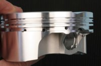
piston ring gap?

I am Carbon

shade tree mechanic
Messages
4,156
Reaction score
199
Points
63
Location
Fort Myers,Florida
I have the big fin 80mm kit from Mikes xs.
I haven't been able to find out what the piston ring gap is.
Does anyone know what the gap should be?
Thanks for any help with this matter.
 
The old .004-.005" per inch of bore rule should get you pretty close. Then .006" per inch of bore for the oil ring. However, this is an automotive, water cooled rule. I seem to recall my Clymer manual listing the factory ring gaps around .011"-.013", but I don't recall exactly so I may be off a bit on this figure. Since your bore is larger and I imagine you are doing a performance build of sorts I would think the figures I listed would serve you well.
 
That is a good point 5twins. Carbon, you can look at your piston and see if you have an anti-flutter groove in between top and second ring. This will usually serve the same purpose as opening bottom ring gap. Flutter is generally only something that higher rpm engines would have to deal with but the XS would fall into that category near it's redline. I don't know typically how high you guys rev these things but I have seen some on here talk about 9K potential. Probably shaking like crazy at that rpm.
 

Attachments

  • piston.jpg
    piston.jpg
    31.9 KB · Views: 374
Last edited:
Thanks Guys. I will go over this info.
I just got back home I will get to reading.
I will make sure that I understand 100% before I file anything "if any filing needed".

There is more to this than one would think. Thanks again Guys
I will be back.
 
here is what I have
Now the bore is 3.125"
Then 3.125" x .004" = .0125" for the top ring
And 3.125" x .005" = .01625" for the second ring.
oil ring 3.125" x .0354" = .110625" for oil rails
oil expander ring no gap
---------------------------------------------------------------------
My manual says
Topl2nd ring (0.0079 - 0.016 in)
Oil control (Rails) (0.0079 - 0.0354 in)
It would appear I don't have the correct tools though
Here is my piston and rings
 
I wouldn't go that big on the oil rails. I'd keep it down near their minimum, like .008" to .010". They're very thin and wear away faster than the upper rings. I set my second ring just slightly larger (about .010") than the top one (about .008"). Chances are, you won't need to do any filing. The rings are usually fitted up pretty good, but do check them. Usually, you'll find the gaps a bit larger than the minimum, not too tight.
 
Looks like there is no anti-flutter groove on that piston so I would follow 5twins recommendations for the gaps. I was using 80mm converted to inches and got 3.149 I believe and that's how I got the gaps I gave to you. I have never ordered that kit before so the bore not be exactly 80mm, might be closer to 3.125 as you measured. And I believe you used .035" x bore instead of .006". That is why your gap number for the oil rail is .110", definitely way too much there.

As far as the tools needed, you can square up the ring an inch or so down in the bore using the piston as long as the dome doesn't travel all the way to the end of the piston itself. I have a ring squaring tool that is adjustable for different bores, comes in handy. Also as 5twins mentions, you may not even need to cut the rings. If you do, you can get a manual grinder from summit or other mail order facility. I use an electric one but I use it almost everyday and wouldn't waste the money for a one time use.

As for the rings, if one is wider as you mentioned then it will be hard to mess up the installation because they typically won't go in the bore if they are in the wrong groove. Top ring is usually made of a better material like ductile iron or steel and you will feel the tension difference when you install it. Bottom compression ring is usually cast and much weaker. Most rings will have a dot to indicate the top side when installing. If not, most top rings will either be non-directional or have a chamfer on the inside of the ring which faces up about 90% of the time. 2nd ring is usually a compression/oil control ring and will have a scraper (dykes or napier, you can view images online) and this scraper will be on bottom outside of ring (faces down).

There are a number of ways people like to "clock" rings so that the gaps are not all lined up when you install them. I generally clock them so that none of the gaps are over either skirt. That way you don't have to worry about which skirt is thrust side and anti-thrust side when there is an offset wrist pin. But to be honest, it doesn't make a whole lot of difference, the rings will sometimes rotate in the bore while it is running so just as long as they don't all line up when you install them you should be fine.

You can install the rings with a ring install/removal tool, there are several different designs on the market or you can roll them on by hand if you are careful. I am not a big fan of rolling on rings because they can get deformed in the process.

Good luck to you, if you need any more help just hit us up. It is nice when I can help someone out on this forum because I generally am learning since I know very little about these bikes.:)

Oh and thanks for the video, makes it a little easier to see what you are dealing with.
 
Last edited:
Thank You very much Gentlemen.
Yall have been a god send.

Josh my video didn't pick it up but there is that anti- flutter groove between one and two. It is small but it is there.
I will be careful when performing the procedure.

Thanks again Brothers!

And yes the videos have been helpful for me to get help on forums.
it's like bringing the pros home with me.
I would not have attempted building this bike without this site.
 
I got a reply from Mikesxs.
I thought I would show you Guys the info.
pretty much the numbers You told me
The ring gaps are pre-set by the manufacturer.

Top and Middle ring.(2-.4mm.) (0.0078" -- 0.0157")

Oil control rings (.2-.9mm.) (.0078" --.0354")
-----------------------------------------------------------------------
My target numbers
So top at (.008")
second at (.010")
oil rail at (.008" to .010")
expander (no gap)
 
I bought the bigfin kit when it first came out and mike was mike. His instructions reads. Always check piston to cylinder clearance and piston ring gap before assembly. Piston to cylinder clearance is 0.06mm (.00236") Maximum clearance when new is 0.07mm. (.00276") Minimum clearance new 0.05mm. (.00197). Minimum clearances above should only be used if initial break in is done when weather is cool. A 200 mile break in period is recommended and the oil be changed at 50-100 miles. Measure piston to cylinder clearance at 90 degrees to the piston pin with the piston in the bore and at about 1/2" into the bore.
 
Carbon, those gap figures would put you at around .003 per inch of bore. Sounds a bit snug to me but if others have runs these gaps before and gotten away with it...maybe they can chime in here.
 
good morning Josh.
The ring gaps are pre-set by the manufacturer are
Top and Middle ring.(2-.4mm.) 0.0078" -- 0.0157")
Oil control rings (.2-.9mm.) (.0078" --.0354")

And the numbers that I have posted are indeed the minimum.
So top at (.008")
second at (.010")
oil rail at (.008" to .010")
expander (no gap)

Also 5twins has been many of these engines.
His suggestion numbers are the numbers I have posted.

I will check all the gaps and record them.
Then I will know where I stand.
I am thinking that I will not have to change them at all.
I'll post the numbers here before I install them.
 
The ring gaps on the original mikes instructions. Minimum ring gap is 0.3mm (.01181) Maximum compression ring end gap is O.07mm (.0030). Ring end gap is checked with the piston ring placed squarely in the bore at leas 1/2" into the bore These are what Mikes instructions gave. I will leave it to the experts to comment on the numbers. The O.3mm looks like oil ring numbers.
 
Back
Top