Turn signal diodes /relay for single led indicator?

Dakota_Lew

XS650 Agronomist
Messages
200
Reaction score
3
Points
16
Location
Badlands ND
I have searched the forums but can't get quite what I am looking for so I need some confirmation and help on my thinking.

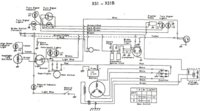
Problem: I have a single led indicator light (not stock, custom) that let's me know when my turn signals are on. So I have to wire each signal line to the same indicator light. (Schematic below) but if I do that it will make both lines hot instead of just the desired side.

Solution: I have two from what I can figure out. Wire In a relay of sorts to do what i want... But I was really wondering if I could find (which I haven't) one way diodes to solder them into the lines. The diodes may be just a mess of an idea...

Is my thinking correct or is there a better way? It just seems like a lot of work and there must be a better solution. Thanks guys.

image.jpg
 
The easiest way is to have an incadescent indicator bulb tied to both flasher lines. Then when one side is 'hot', the other side acts like a ground for the indicator. Two higher wattage signal bulbs in parallel present enough of a low resistance to sufficiently ground the indicator, and the low current thru the indicator isn't enuff to light those 'grounding' signal bulbs.

But with an LED, you have a polarized circuit, and it'll only work in one direction. So, you can tie diodes, one each, to the signal lines, feeding to the LED indicator. That'll prevent the two sides from cross-feeding each other.

In your diagram, above, replace the (2) question marks with (2) diodes...
 
The diodes should have the bands printed on the case pointed toward the light, band ends tied together there and to the light, in other words. 1N4001 thru 1N4004 will work, cheap, and at Radio Shack. Looks like a good opportunity to change to two indicator lights. A triangle LED light would be great, have one angle pointing the direction.


Better yet, a single, simple, bi-color LED for the indicator, red for right and blue for leftist :)
http://pinout-circuits-images.dz863.com/134/LTL-30EHJ-002A.jpg
 
Thanks for the reply. Ok so i am going to go the diode route then.

Can you confirm that these diodes will work. (http://www.amazon.com/100PCS-Diode-...8&qid=1388422038&sr=8-1&keywords=1n4001+diode)

Side note: I live 3 hours from any sort of town so i have to have stuff shipped in and this is the cheapest with prime account.

Yes, the 1N4001 will work. Its rated at 1 amp, and your LED indicator draws only 10 or 20 milliamps. However, just as TwoManyXS1Bs said, a simple and cheap way to go, is to just connect a pilot lamp 12v, 3.4 watt incadescent bulb from the left turn side wiring to the right side turn wiring. You may already have that type of bulb because its the stock bulb used in the speedo and the tach.
 
^The problem with the easy way is there hasn't been a description yet that's clear to someone who doesn't already know the trick. It sounds like you're saying just connect the two sides together via the bulb, and that bulb becomes the indicator, correct?
 
Thanks again for the reply, i understand your points on the incandescent bulbs, clever trick that i didnt put together. I don't have a stock indicator, I have custom cobbled together from left over parts from other builds.

I got those diodes from amazon, should work great for what i want and the right price.

Thanks for all the advice guys! I will let you know how it turns out.
 
I wanted to swing by and meet you, and gggary as well, when I was up there last spring and my seasonal job and the housing that came with it ended. But I had to dash south instead of east while it was clear. Actually I stayed there a month longer than I was supposed to while I waited on some passage to clear.
 
^The problem with the easy way is there hasn't been a description yet that's clear to someone who doesn't already know the trick. It sounds like you're saying just connect the two sides together via the bulb, and that bulb becomes the indicator, correct?

Yes that's correct; its extremely simple................dark green wire to one side of the bulb and dark brown to the other side of the bulb. No ground required at the bulb itself. The ground path is supplied by the 2 #1156 bulbs on the side that is not flashing. The 3.4 watt bulb flashes as an indicator, with the majority of the voltage drop across the 3.4 watt bulb, while the two 27 watt signal bulbs carry the small current to ground, but do not flash themselves due to the low voltage across them.
 
^The problem with the easy way is there hasn't been a description yet that's clear to someone who doesn't already know the trick. It sounds like you're saying just connect the two sides together via the bulb, and that bulb becomes the indicator, correct?

Yup, it's that easy. Look at the upper-left corner of this diagram:
 

Attachments

  • XS1-XS1B-Schematic2.jpg
    XS1-XS1B-Schematic2.jpg
    261.4 KB · Views: 720
Last edited:
That way won't work with LED's. The LED indicator only passes electricity one way.
LED turns won't draw enough current to light an incandescent indicator.
To get the led indicator to light on both sides, hook the diodes in. Run one diode from the right side, one from the left. Hook them together and hook to the positive lead of the indicator, ground the other lead.
Leo

Yes Leo, I think we are all in agreement. TwoManyXS1Bs stated it clearly back in post #2. No mention of LED turn bulbs from Dakota_Lew, so the assumption is he using stock 27 watt bulbs for turn lights, but wants to use an LED as an indicator only. So, two ways to go................either 2 diodes and 1 LED indicator, or just use one incasdescent 3.4 watt pilot (meter) bulb as an indicator, with no diodes required.
 
When a signal bulb burns out there isn't enough load on the flasher to flash when it's switched to that side, so the indicator bulb and the remaining signal bulb on that side stay on steady, telling you a light is burned out; a feature which causes a problem when you change to leds with their lower load to start with. So goes my theory. An asset becomes a liability...
 
I guess I missed that, He did mention LED as the indicator. The diode's would work. Being LED the indicator is probably in a replacement speedo. So putting an incandescent bulb some where isn't an option.
Leo
 
I am sorry, yes everything is LED, signals and indicators. I went with using the Diodes, My wife is going to town tomorrow so i will report back when i get them wired in. Thanks guys.
 
I am sorry, yes everything is LED, signals and indicators. I went with using the Diodes, My wife is going to town tomorrow so i will report back when i get them wired in. Thanks guys.[/QUOTE

Well we gave advice based on what you told us, but you failed to mention the LED turn lights. You can disregard anything we said about incadescent bulbs or 27/3.4 watt bulbs.

Do you have a flasher unit that will work with the small current used by the LED turn signals?
 
Yes and yes, this is the sixth xs650 I have rewired but I wasn't sure of the solution and I knew some one out there had more knowledge then me. The problem with diagnosing an issue is you might now know all the details that matter such an incandescent bulb hence the question. I knew i was missing something, even though Occam's razor seemed to prove the solution which was diodes in this occasion. Regardless I would have never put the incandescent bulb together, so I learned something there for sure, so thank you.
 
The diodes worked great, i ended up using the 4004, i wired them in just like my above post where the question marks were.

Thanks for all the help!
 
Back
Top