Digital Voltmeter, Clock and Temperature module

TwoManyXS1Bs

BBQ Hunter
Top Contributor
Messages
14,670
Reaction score
15,294
Points
813
Location
Fredericksburg, Texas
Another inexpensive voltmeter, now with clock and temperature probe!

This is the original thread:

Inexpensive voltmeter, monitor voltage while riding

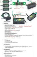
I've had my eye on these newer Volt/Time/Temp displays for quite awhile now, and finally decided to get some to see how well they work. They run as low as $12 on eBay.

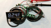
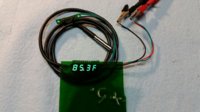
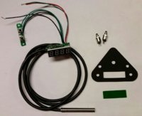
There's a large version that displays Voltage, Time, and Temperature in degrees Fahrenheit, with a remote probe.
3Way-VoltTimeTemp01.jpg

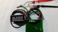
There's also a smaller version, about half that size, identical features, but the temperature display is in degrees Celsius.

3Way-VoltTimeTemp02.jpg
 
Both versions tested fine on the bench, voltage and temperature readings were fairly accurate.

3WayDisplay01.jpg

But, I don't care for the appearance of the unlit LED segments, makes it hard to read.
A translucent green diffuser lens really cleans that up.

3WayDisplay02.jpg
 
The mount plate uses the old ignition switch location, with 50mm screw centers. The larger unit is too big to fit in there. And, being a hard-headed American, I wanted the temperature display in Fahrenheit.

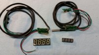
The pin-outs of the digital displays are identical, so I removed both digital displays.

3WayDisplay03.jpg

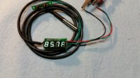
And soldered the smaller display onto the Fahrenheit module.
Now I've got a smaller unit with Fahrenheit display.

3WayDisplay04.jpg

Much better with the green diffuser.

3WayDisplay05.jpg
 
Now, the 2nd half of the challenge: Where to fit the temperature probe?
The temperature limit for the display is 125°C (257°F), but the sensor is rated to handle up to 300°F.
I want to monitor sump oil temp, but don't want to irreversibly modify any rare/antique engine parts.

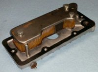
But, the non-rare sump filter plate is fair game. Got a spare unit off eBay.
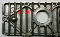
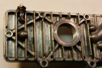
Found a suitable, but cramped, location alongside the sump filter.

3WayDisplay07.jpg

The hollow stainless-steel 6mm probe measures about 0.236" diameter.
A 15/65" (0.234") drillbit makes for a snug press-fit mounting hole.
Also, wanted the probe hole to be between sump cover fins.

3WayDisplay08.jpg
 
hate to answer a question directed at someone else, but a tight fit provides its own seal and looking at the numbers it's pretty tight... although a smear of hylomar or *branda*bond 1104 etc wouldn't hurt.
EDIT .002" isn't a great deal but as an interference fit, remember the hole is .002 smaller than the probe OD... end edit.
I'm curious though, TwoMany, you say the probe is hollow, might the lack of solidity work it loose over time? maybe something to watch for which I'm sure you'd be on the ball anyway.... how might temps affect probe and casing metals at operating temp? case expansion, probe compression... I'm thinking bimetalic and expansion rates. how thick are the probe walls, any idea? maybe some kind of external captive might be a good idea or maybe unnecessary... just throwing a dumb fly in your ointment lol. I do like the idea and hope it works well. I respect your efforts, ingenuity and knowledge whole heartedly. My questions are more out of ignorant curiosity than educated doubt.
 
Last edited:
Ha, ha, ha................Give an explanation ............then...........:gun: shoot your explanation to bits
 
Ha, ha, ha................Give an explanation ............then...........:gun: shoot your explanation to bits
isn't that how science tries to evaluate itself and how engineers test their shit?

I didn't really shoot anything to bits... I only asked questions based on Angus' question and gave a reasonable answer to it in the first place. :bird:
 
Youze guyz crack me up. I guess that I should've continued posting, showing the probe fitment, but I ran outta steam. But, yes, thinking on how to fit and seal the probe did consume some grey matter.

I would've preferred to use a typical automotive type screw-in temp sensor, but this gadget uses a Dallas Semiconductor DS18b20 temperature sensor, in a TO-92 case. Looks like a transistor, but it's really a network-addressable microprocessor with its own temperature sensor (I suspect using a diode's Vf temperature slew). It communicates thru a single-wire bus topology to a master processor, and delivers temperature info in a 9 or 12 bit data block. Very accurate, no analog temp-varister inconsistancies. A popular item in the Arduino cult. But not in cars yet.

So, in the next couple posts is the probe fitment. Press-fitted with a thin coat of JB-weld. Kinda similar to the press-fitted oil gallery plugs found everywhere on aluminum bike engines.
 
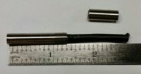
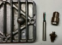
The probe is too long, so it's shortened to 1.300" max.

3WayDisplay09.jpg

I had ordered some sealed 3-pin flat micro connectors for this project, but what was delivered some 4-pin large Molex connectors.
Oh, well. Digging thru the junkboxes yielded some suitable WW-2 era Winchester connectors that should work.

Shortened probe and connectors ready for fitment.

3WayDisplay10.jpg
 
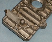
A ring of JB-weld is applied around the probe base, then press-fitted, wires first, downward into the hole. The excess epoxy forms a sealing ring at the base of the probe.

Connector and wiring is soldered, then epoxied to the sump plate.

3WayDisplay11.jpg

Testing the system.
You can see the little ring of epoxy at the base of the probe.

3WayDisplay12.jpg

Then seal it all up with a blob of epoxy.

3WayDisplay13.jpg
 
Sump filter mounted, gasket greased up, ready to mount.

3WayDisplay14.jpg

Sump cover with filter and probe mounted.
Cable tucked away, and routes alongside the alternator harness.

3WayDisplay15.jpg

Yes. That's 44 year old grunge in there...
 
It looks the business and the write up sounds the business. should have known you're not the kinda guy to just shove it in there without having it all worked out.

"Dallas Semiconductor DS18b20 temperature sensor, in a TO-92 case. Looks like a transistor, but it's really a network-addressable microprocessor with its own temperature sensor (I suspect using a diode's Vf temperature slew). It communicates thru a single-wire bus topology to a master processor, and delivers temperature info in a 9 or 12 bit data block."

sounds like you just casually borrowed a part from some future-tech robot with self aware AI that you're building on the side :laugh:

please excuse my earlier under thinking, over thinking and over typing.
 
...please excuse my earlier under thinking, over thinking and over typing.

Not a problem, TLCbobber. In fact, the interaction is quite helpful. All this bike stuff can be difficult to solve and explain, and community involvement adds to, and helps clear-up, the thread. Keep it coming.

Been doing other maintenance and nit-pic things on the bike, ran outta steam again. Will post final fitment and testing later...
 
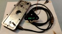
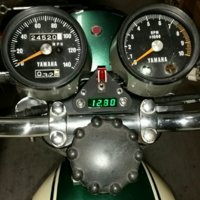
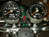
Here's the unit mounted in the old ignition switch location.
It can be set to cycle thru the 3 displays, 5 seconds per display.

Voltage ---> Temperature ---> Time

3WayDisplay16.jpg 3WayDisplay17.jpg 3WayDisplay18.jpg
 
Well, it's around 100°F out there. I was planning on riding and testing the Volt/Time/Oil-Temp display, but this little one said "Don't go out there!".
DontGo.jpg

So, I waited until just before sundown, when it cooled down to about 93°F.

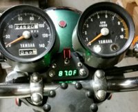
Here's the display unit during bike warm-up:


And, after a short 6-mile run. Oil temperature got up to 214°F.

I'll try for a "Peak heat of the day" later. Curious to see how hot the oil gets...
 
Back
Top