Wiring in a replacement solid state rectifier/regulator (not a nylon screw thread)

MOSFET

XS650 Enthusiast
Messages
42
Reaction score
4
Points
8
Location
Estland
Hi.

First, let me explain what is going on. I'm in the middle of turning my 1979 XS650 Special in to a cafeish custom bike, and that includes building an electrical system from scratch around the Motogadget M-Unit. Took these pictures today:

(the polystyrene seat is there temporarily, trying to work out the shape)
sikl_zps61d24af4.jpg


Motogadget M-Unit and MMB 48mm (1 7/8") electronic speedo (gen II, model Target)
WP_20150118_0051_zps835fb868.jpg


Now, to the point. My XS is an euro-spec, and the problem I have has to do with the field coil of the alternator. I got my self a solid state replacement regulator/rectifier unit from Electrosport (model ESR350, advertised as a straight replacement unit for the old points ignition models), because the original rectifier was all corroded outside and we all know that the mechanical regulator is pointlessly oldschool.

New
WP_20150118_010_zpseed0d638.jpg


Old
WP_20150118_009_zps8b6a4e6e.jpg


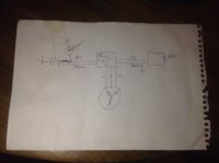
My field coil has two wires, a black one and a green one. In the old wiring the black one was tied straight to ground, and the green one went to the regulator. From that it is safe to guess, the old mechanical regulator was switching on and off the positive side of the field coil through the green wire. And that is all fine, but it was kind of surprising to read from the Electrosport manual (PDF file link) that the field coil's ground is switched on and off through the green wire with the new unit. So there lies my question, should I just connect the new unit's green wire to the black wire of field coil (both ground now) and connect a (ignition) switched positive to the green wire of the field coil?

Bottom one green, upper one black
WP_20150118_007_zpsc04dce20.jpg


After discovering my problem, I started searching for field coil electrical schematics on this forum, and found out that most North-American XS650's have the regulator switching the ground side of the field coil, I wonder why is it the other way around on euro-spec models.


Thanks,
Kustas
 
Last edited:
Their statement "switched ground output" is not correct. The green wire from the rec/reg unit actually provides a variable positive voltage. The green wire must connect to the outer brush which is the botton terminal. The brown wire from the rec/reg is the voltage sensing/current supply for the field winding (rotor). That brown wire should connect to the load side of the ignition switch, which is the same electrical point as the common fuse panel input.

On north american bikes, there were 2 ways to wire the charging system.

1970 to 1979; one end of the field winding (inner brush/slip ring) is at ground (battery negative), and the regulator supplies a variable positive voltage.

1980 to 1983; one end of the field winding (inner brush/slip ring) is at full battery + voltage, and the regulator supplies a variable negative voltage. Both brushes are insulated from ground with this method.

Edit:The field coil has no required polarity...................the current can flow either direction. Regardless of the current direction, the spinning rotor has half north poles and half south poles, and that gets the job done.
 
Last edited:
Thank you for your thoughts, rg.

After reading your post, I thought how could I do a simple test to prove whether your statment is correct or not (about green being a variable positive on the new unit), so I did a bench test with my battery. Giving that there is only battery +12 V coming in through the brown voltage sensing wire to the rec/reg unit (+12 V is too low, and the field winding should be turned on at this point), it should then provide a positive signal on the green output, which it did, which means you are correct.

So I was wrong about the difference in euro-spec na-spec models, the difference (which field winding side is switched in the regulator) is in the ignition system. Mine is a 79 points ignition model, so it'll have the positive side of the field winding switched on and off, just like you stated.

Thanks again,
Kustas

I'm glad you checked, because no one should totally believe every thing they read on the world wide web. WWW is full of myths and half truths.:D
 
Their statement "switched ground output" is not correct. The green wire from the rec/reg unit actually provides a variable positive voltage. The green wire must connect to the outer brush which is the botton terminal. The brown wire from the rec/reg is the voltage sensing/current supply for the field winding (rotor). That brown wire should connect to the load side of the ignition switch, which is the same electrical point as the common fuse panel input.

On north american bikes, there were 2 ways to wire the charging system.

1970 to 1979; one end of the field winding (inner brush/slip ring) is at ground (battery negative), and the regulator supplies a variable positive voltage.

1980 to 1983; one end of the field winding (inner brush/slip ring) is at full battery + voltage, and the regulator supplies a variable negative voltage. Both brushes are insulated from ground with this method.

Edit:The field coil has no required polarity...................the current can flow either direction. Regardless of the current direction, the spinning rotor has half north poles and half south poles, and that gets the job done.
Hey guys!

I got the same setup on my bike. Just got this solid state rectifier/ regulator.
It sounds like you know what your talking about and I need some help on the wiring if you don't mind.

-Green wire from the rectifier hooks into the rotor green wire
-Black from the rectifier hooks up to black on rotor
Brown from rectifier hooks up to load side of switch? Does it matter if I hook this up to positive side of batt?
-Red hooks up to positive terminal on batt?

I appreciate the help!
 
...Brown from rectifier hooks up to load side of switch? Does it matter if I hook this up to positive side of batt?
-Red hooks up to positive terminal on batt?

Don't connect it directly to the battery.
It'll stay on, heat up the rotor, and drain your battery...
 
Don't connect it directly to the battery.
It'll stay on, heat up the rotor, and drain your battery...

Oh that makes sense.

Brown acts like a control wire to turn off the circuit when the bike is off.
Is that the wire that is controlling the voltage to the field circuit and red is the dc voltage shooting out of the rectifier that charges the batt?
 
Hi,im a new guy on this forum but have owned many xs's over the years.I have one now which i will go into more detail about if requested.Anyway i always used Honda Superdream reg/recs on my bikes and never had any problems.
 
Ok I just wired everything and I'm getting 20v at idle and the rectifier/v regulator gets pretty hot quick.

I wired the brown wire to the positive terminal on the batt and left the red unhooked. I then hooked up my multimeter to the red wire and that's where I'm measuring the 20v.

I'm not really sure what's going on... I already tested the rotor and stator for shorts. Everything checks out fine.
 

Attachments

  • image.jpg
    image.jpg
    110.4 KB · Views: 664
to the OP, how did it turn out and what didi you end up doing to the stator wiring and M-Unit? (I'm running the M-Unit, the Mikes' XS reg/rec in a 1975 with the original stator.)
 
Young, the 20 volts maybe just fine, I never tested the red wire without it being hooked to battery positive.
Hooking the brown wire straight to the battery is not the way to do it. It needs to hook up after the main switch. See post #6.
The reg reads the voltage on the brown wire. On the 70-79 regs if the voltage read is below the preset voltage it turns on the rotor by sending full battery voltage to the rotor on the green wire, through the rotor to ground.
On the 80 up bikes, battery voltage fed to the rotor on a brown wire to one brush. The green wire runs back to reg/rec.
The reg/rec reads battery on the brown wire. If low it turns on the rotor by grounding the green wire.
On the rectifier there is a red wire that feeds the alternator output directly to the battery positive. The black wire goes to ground. Not at the brushes but any good frame ground. This provides the full circuit for the alternator.
So on your reg/rec the red wire should go to the battery. Black to ground. Green wire to green wire.
For your testing the brown wire to battery is ok, but once you wire the bike have the brown wire hook after the main switch.
In one post you ask if the brown wire controls the voltage to the field circuit, NO, the regulator controls the voltage to the field circuit. Early by turning the power on/off, later by turning the ground on/off. The brown wire on the early supplies a voltage to be read and the power for the reg to send out to the rotor. Later, it only supplies a voltage to be read.
When the bike is off no power flows on the brown wire so no power can flow through the rotor. When the bike is on then power can flow through the rotor, that's why the brown wire to the reg needs to be after the main switch.
Leo
 
Just wanna say........I have that same unit on a Honda 750 Custom. My RR unit has a charging cut off point of 13.6 volts. I swapped this R/R to my other 750 Custom, same result, one bike charging at 13.6 and one at 14.7. Both of these bikes are in great shape with healthy charging systems, that one R/R just has a different cut off point, charges the battery and works fine, just calibrated different.

Scott
 
to the OP, how did it turn out and what didi you end up doing to the stator wiring and M-Unit? (I'm running the M-Unit, the Mikes' XS reg/rec in a 1975 with the original stator.)

Stator wiring? You mean rotor wiring?

My solid state Electrosport rectifier/regulator has not worked properly since day one. I ended up using a combination. I am using the Electrosport rectifier part, but had to hook up my mechanical voltage regulator also, because my Electrosport voltage regulator part is absolutely dead, and will apply as much VDC on my battery as much the rectifier can rectify from the 3-phase VAC.

Here is the moral of my story, please always check your newly bought equipment before installing or modifying it to your bike. I cannot return it, because I modified the connector before actually trying it on my bike. Stupid.

QWERTYMage, do you need help with wiring up your M-Unit? If you have questions, feel free to ask, mine has been working perfectly since last spring. Beautiful thing this Motogadget M-Unit.

EDIT: I will post up my custom wiring diagram for my bike after work, so you can follow that to hook up your M-Unit, and charging system. I read from your other thread that you run a pamco ignition, mine still has the points ignition, so you'd have to ignore that part of the diagram.
 
Last edited:
Okay, here is my original wiring schematic that I made for my motorcycle. It's built from scratch, so it means no original bike wiring will connect to it, with the exception of the alternator. It is meant for older points ignition XS650 model, and will work with Mikesxs solid state regulator/rectifier (points ign. version #24-2089). Will not work for newer electronic ignition models, where the alternator rotor field coil is hooked up the opposite way.

Mikesxs Rectifier/Regulator connection:

-Red to battery positive
-Black to battery negative (ground/frame)
-Brown is voltage sensing, so it connects to the aux port of your M-Unit
-Green is your alternator rotor field coil positive side (switched +12 V)
-3 white wires connect to your stator in random order, 3-phase AC will be provided through these to be rectified

Do not try to combine my design to your existing original wiring, it might not end up well. If you do not know electrical basics, do not attempt this job.

Click on the schematic to zoom in


My wiring schematic is missing the ignition lock part and speedometer speed hall sensor.

23991561efd506_l.jpg


23991565e30491_l.jpg


23991567cfb098_l.jpg


239915697f8736_l.jpg


23991573d5c2bd_l.jpg
 
Last edited:
dude. yes. wow.

Any surprises by the kit?

Are you running single filament brake/running setup?

ANy other hints yo wanna share?
 
dude. yes. wow.

Any surprises by the kit?

Are you running single filament brake/running setup?

ANy other hints yo wanna share?

Im running a led tail light with only the brake side connected. The PWM will dim the brake light to running light with around like 60 Hz pulses, which will give a kind of ghost effect when you move your eyes over the light. Very much a safety feature in my eyes, your tail light will not melt into the background for sure.

Wiring up the M-Unit is quite straightforward. I highly recommend getting the Motogadget Cable kit for your project, and wire everything from scratch, it will make your life a lot easier (and cheaper) in the long run. Throw the original wiring away.

Also, get your self some Japanese bullet connectors, blade connectors, and a proper crimping tool. Here is a few more pictures from my build


This thread makes me want to tear out all my wires and start over. Looks great Mosfet
 
Mosfet,

This is awesome. Thanks for the help.

What program did you use to make your wiring schematic? It's really nice and clean.

I am using the Motogadget wiring kit, ferrule ends, crimp/solder/shrink butt and spade connectors and a marine main fuse from DelCity, and 2 quick disconnect blocks in the whole system. Super clean and correct is my goal.

I'll be running dual intensity brake/turns (Brake/running on one wire, turns on the other... I hope.)

http://www.hightechspeed.com/products/XArc/index.asp

Cheers.
 
Back
Top