Regulator Rectifier Conversion (again)

ebb0tk

XS650 Addict
Messages
123
Reaction score
13
Points
18
Location
Sweden
Hi, i have a 1981 XS650 European (with points)

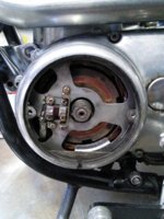
Posted pics of the alternator etc.

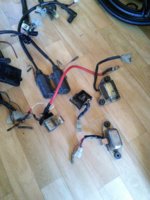
I have trouble finding decent VR-115 Regulator on eBay.

Are there any other regulator's i can use? Points towards ebay link would be good.

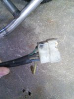
And as for rectifier aswell, link towards eBay there would be nice too.
Been looking at this rectifier, but how are you mounting em?

http://www.ebay.com/itm/SQLF30A-Alu...nals-Diode-30A-1200V-/151314178350?rmvSB=true
 

Attachments

  • IMG_20170719_114329.jpg
    IMG_20170719_114329.jpg
    298.7 KB · Views: 540
  • IMG_20170719_114141.jpg
    IMG_20170719_114141.jpg
    251.9 KB · Views: 606
  • IMG_20170719_113650.jpg
    IMG_20170719_113650.jpg
    239.4 KB · Views: 862
There is a recent thread by Mailman where he deals with rectifier issues starting at Page 18:

http://www.xs650.com/threads/stella-1977d-survivor-back-on-the-road.47329/page-18

Very good thread with loads of information from many forum members. 5twins added some very nice photos of his rectifier and regulator handy work.

Regarding rectifiers, I always buy good quality via the authorized agent, some of which appear on Ebay. I suspect the cheap Chinese rectifiers sold on Ebay may not always be of a good quality when bought via a third party. I have used a cheap one in my MIG welder with not problems, but others have been less successful. On this Forum there are mixed reports on the quality of cheap rectifiers. I used a Vishay 3Phase rectifier for my bike as it is a quality product and they now own International Rectifier. Mine cost maybe 3x the cost of a cheap Chinese product offered on Ebay.

Also, it would be a good idea to install a voltmeter on your bike so you can monitor the charging system when riding.
 
Cool, im doing a complete new harness. I may do the nylon screw mod, to use another regulator. Anything specific to keep in mind if doing the nylon screw? Or can i look at a '81 USA wiring diagram and wire the alternator like that?
 
I am not to sure what your objective is. Your photo suggests you are making a custom modified bike, or is that newly welded frame something unrelated? If you give a bit more background to your plans then the forum members will be better able to assist you, and they are very good!

If you do the nylon screw modification then that is usually associated with the Type A regulator/rectifier combination. This combination unit is quite large at 80mm x 65mm x 30mm. My view, from what I have seen on this Forum, is that it is easier to find places to mount the older style separate rectifier and regulator units. On the positive, new combination units are available and look quite smart and modern.

You may be better to use a simplified wiring diagram if you are making your own harness. If you go to the Tech Section then the diagrams are right at the start under Electrical. There are various levels of complexity depending on what systems/services you want on your bike.

The US SH wiring diagram has several features which make the wiring more complex e.g. reserve lighting, auto indicator cancellation and safety interlocks for the electric start. If you want to make your own harness then decide what features you want first.

Many will be pleased to see you are planning to keep the original alternator, it is an excellent charging system.

Best of luck and keep in contact.
 
Yeah well my rectifier is totally corroded and pretty beat up. Im building the bike from scratch and been reading through some threads about the Chrysler/radioshack mod and came up with these parts:

http://www.ebay.com/itm/151314178350?rmvSB=true
http://www.ebay.com/itm/NEW-Voltage-Regulator-Alternator-Fit-For-Fiat-Strada-124-128-VR170/331348615760?ssPageName=STRK:MEBIDX:IT&_trksid=p2057872.m2749.l2649

Im having a pre 79 model alternator, which what ive been reading needs to be ungrounded with nylon screws when using those 2 items?
But my main question is: How are you wiring those 2 units up to the bike?
 
Note: Negative = -ve Positive = +ve


The alternator has 3 Yellow (Edit: Actually White) AC output wires - These are the three phases and they are wired to the phase terminals on the rectifier in any order. The AC from the alternator is converted to DC and because there are 3 phases the output DC current is quite smooth.

The DC output terminals will probably be marked as + and - .

The + output from rectifier goes to the battery +ve via a fuse (20A).
The - output from rectifier goes to the bike frame and then to the batteries -ve terminal.

The voltage reaching the battery needs to be controlled at about 14.1 to 14.5 volts in order to charge the battery efficiently. But the voltage from the alternator/rectifier depends on how much current is flowing through its rotor winding via the brushes.

The Regulator monitors the voltage at the battery +ve terminal and if it is too high the regulator reduces the current though the rotor. If the voltage at the battery is too low then the regulator increases the current through the rotor. The regulator is constantly adjusting the rotor current to keep the charging voltage fairly constant. My charge voltage varies between 14.1 and 14.3 Volts.

I do not know for sure what the VR-170 Type is A/B? I will assume here it is a Type A.

On an XS650 with a Type A regulator, +ve power is supplied to one rotor brush. The other rotor brush goes to the frames earthing via the regulator. On the VR-170 (assuming Type A) the Red wire is a sensor and goes to the +ve line of the battery and monitors the voltage coming from the rectifier. The Green wire goes to the other rotor brush and on an XS650SH (US) the wire to the brush is coloured Green. The regulator controls how much current passes from the brush through the Green wire and then to the bike frame and battery. The regulator case must be earthed to complete this circuit.

The Red sensor wire is normally wired to the ignition switch.

I hope this helps you out, but if unclear let me know.


(Please check that the VR-170 is Type A)

Note: Type B regulator controls the current entering the rotor and it exits directly to earth. This is why one brush is earthed. When you covert from Type B to Type A the brush must be isolated from earth - hence the Nylon screws and some minor wiring changes.
 
Last edited:
Yes, what ive been reading its a Type A regulator. Wire it up like this? But i have a green and BLACK wire from my brush, since its a pre 79 alternator.

combo3.jpg
 
In that diagram you included from Pamcopete he is using two fullwave bridge rectifiers wired as a 3Phase rectifier. 3Phase rectifiers are also available in that same square package but have 5 connectors instead of 4. See the following thread when I made my unit:
http://www.xs650.com/threads/xs650-specials-electronic-rectifier-and-regulator-units.48291/
My unit was not as tidy as I would have liked because I could not get hold of a VR-170 type package which can be bolted directly to earth on the heat sink. But it is still working.
 
Last edited:
Indeed, but for reference only how to wire up only the "rectifier".
Im only confused where the black wire from the brush goes?
 
Wiring up a 3Phase rectifier

The rectifier has 5 terminals:
  1. One terminal is + and goes to the Battery +ve via a fuse.
  2. One terminal is - and goes to the bike frame and eventually to the Battery -ve.
  3. Three terminals will be marked with "S" meaning a sine wave which stands for AC input. You may also find them marked as 1,2 and 3 or P1,P2 and P3 or in combination with a different letter. The order in which you connect the Yellow (Edit: White) alternator wires to the three terminals on the rectifier is not important.

Black Wire from Brush Issue

When changing from a Type B system to Type A you need to do the following:
  1. The brush terminals must be isolated from the engine: This is the Nylon screw scenario you have read about.
  2. Each brush will now require a separate wire.
  3. One brush wire will pick up +ve power when the ignition is switched on (I think Brown will be the colour of choice here - check the XS650 SH (US) wiring diagram).
  4. The other brush will need a Green wire connected and this will go to your Type A regulator's Green wire.
There are well written accounts for this entire process on this Forum and you should read them to confirm wire colour choice and as to which brush the different colours should connect (I do not believe the order is important, more of a matter of convention). Go to the Tech Page and view the following thread in the Electrical section:
http://www.xs650.com/threads/nylon-screws.6477/

Note: The wires need to be securely fitted in place to ensure the small drive sprocket and chain do not damage them.

I hope this helps.
 
Last edited:
Note: Sometimes the Yellow wires have faded and look White.
I had a big cable once with about ten or twenty wires in it and all the wires were white! Total confusion. Did not occur to me to cut back the outer to see what colors the wire were... One of those things that only happens once.
 
All the 650s I've seen have 3 white wires coming out of the alternator, not yellow ones. Connecting the rectifier is pretty simple. The one you're considering should have a sticker on the side showing the connections. The 3 whites, in any order, go to the 3 tabs in a row on one side. The black and red wires go to the other 2 single tabs on the other side. The red goes to the tab near the red plastic end cap, black to the one near the black plastic end cap .....

C26qkLB.jpg


The black is a ground wire of course. The red runs back to the battery "+" terminal. On the stock harness, it connects to the red wire running up to the key switch, after the fuse and before the key.

If you use the Fiat regulator, you will need to do the plastic screw mod and change some wiring. I would search for a VR115 equivalent first. There are many with different part numbers. They are all the same unit, just from different manufacturers. Here's some you can search for .....

M5-701 12V B-Circuit (Regulated Power)
GRX-528 Motorcraft (Ford)
VR 1010 NAPA Echlin
VR727 Wells
1V1033 Airtex
C622 AC Delco
VR-1760 Ace
VR291 GP Sorensen
RAB 12A6 Electro Systems
R292 BWD
A621
86079
KVR179
AL165F
 
5twins, you are correct, but you knew that already! I just went and checked my alternator wires. They are white at the connectors but uneven yellow under the black insulation. I guess something has stained them yellow. The wiring diagram also states white...........................

........................I stand corrected and it will not be the last time.
 
All the 650s I've seen have 3 white wires coming out of the alternator, not yellow ones. Connecting the rectifier is pretty simple. The one you're considering should have a sticker on the side showing the connections. The 3 whites, in any order, go to the 3 tabs in a row on one side. The black and red wires go to the other 2 single tabs on the other side. The red goes to the tab near the red plastic end cap, black to the one near the black plastic end cap .....

C26qkLB.jpg


The black is a ground wire of course. The red runs back to the battery "+" terminal. On the stock harness, it connects to the red wire running up to the key switch, after the fuse and before the key.

If you use the Fiat regulator, you will need to do the plastic screw mod and change some wiring. I would search for a VR115 equivalent first. There are many with different part numbers. They are all the same unit, just from different manufacturers. Here's some you can search for .....

M5-701 12V B-Circuit (Regulated Power)
GRX-528 Motorcraft (Ford)
VR 1010 NAPA Echlin
VR727 Wells
1V1033 Airtex
C622 AC Delco
VR-1760 Ace
VR291 GP Sorensen
RAB 12A6 Electro Systems
R292 BWD
A621
86079
KVR179
AL165F

Thanks 5twins!!
I got a hold of a VR-115 regulator. Looks like it has 4 wires at the picture.
Green, Black, Yellow and Orange.
How is that wired up?
 
It is your lucky day!!!!! In the thread "my Father in Law gave me a 1979 XS650 and this weekend we rebuilt it. Galleries included" by daniel deblanke there are links to his build photos. One of the photos in the third link is for a VR291 regulator. This is another variant of the VR115. The photo gives the description for the 4 wires:

VR115.jpg


Thank you daniel deblanke.
 
Last edited:
Based on the wiring assignments:
  • Orange provides power to the regulator and this power comes via the ignition switch along the harness brown wire
  • Yellow is a voltage sensor wire and tells the regulator what voltage the alternator output from the rectifier is and then the regulator adjusts the alternator field current accordingly.
  • Orange and Yellow get tired together and take their power via the ignition switch on the brown wire.
  • Green goes to the green field winding wire.
  • Black connects to the harness black wire which is the earth on the bike frame.
On car/van/truck regulators these colors are fairly standard but often the orange wire is red.
 
Last edited:
Caution.........Wiring diagrams posted on here are US specific............US model XS650's changed from points to TCI, (factory electronic), ignition in 1980.........

.In Europe, and Oceania especially, they kept the points ignition through to the end of production.............Using any wiring diagram from the US models after, and including 1980, will not work with the Euro/Oceania models...........

Haynes 1970-1983 manual has both Standard and SE wiring diagrams for UK models..........SE is the UK Special and these have points ignition, as does the Standard. Both these models were sold up to 81 and later in some cases but the model was the 81.

Type B...........points ignition bike..........Using the VR115 regulator, or the equivalent, (refer 5twins post # 12).

Type A....... is for TCI, (factory Electronic),ignition.

Just trying to simplify the difference.............I get confused when there is to much exploitation......not being critical.
 
Last edited:
Back
Top