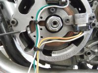
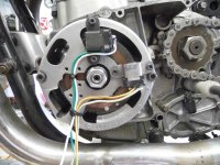
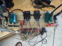
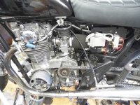
Points to GN250 Electronic Ignition Conversion

The clipping on that one wave will probably go away if you set volts per division higher. Or there might be something to set on the display. The high output means you might be able to adjust timing by moving the pickup in and out, since shrinking the wave effectively changes where in the rotation it crosses the voltage threshold to be detected, depends on how pronounced the ramping up is. Magnetic pickup probably means you can use a steel washer attached to the rotor instead of a magnet. If you want to limit a too high output, a voltage divider look up voltage divider formula, will lower the amplitude without affecting the shape.

That seems as a Splendid idea
A steel washer attached on the rotor can save $ 150 --- $ 200 dollar in fabrication and realization costs and can be moved.
And if need be a much smaller hole -- drilled for fastening. ..perhaps done without removing the rotor
perhaps a quick small spot weld is possible MIG or TIG Some wet rags around for cooling that might be doable or other Maybe soldering with a gas flame . ..
 
what is that O-scope program you're using?
It's called Soundcard Scope. It's basically for looking a sounds but it does have a (very basic and limited) voltage function. Still looking for a better one, but this one works for looking at waveforms and I use the Fluke to measure voltage.
O-scope probes are here.
Also made an adjustable voltage divider so's not to blow out the PC's soundcard. A bit of overkill I know. Here's the link for that.

v divider 2.jpg


v divide 3.jpg
 
If the output is high enough and the ramp slow enough and my theory about amplitude effect on timing is right, then instead of a voltage divider you could use a trim pot wired like a divider and fine adjust the timing by twisting its knob
This whole project is supposed to be cheap and KISS. My goal is a simple trigger as close as possible to the TCI trigger.
 
This is interesting... set up the sensor I'd removed the magnet from and it's still a powerhouse. .025" gap, 1500rpm and it still cranks out well over a volt. The O-scope app is still choppin' at the peaks even at the lowest range. Switching the probe to X10 stopped that, so it's the app itself and not the sensor. Now I'm looking at researching whether or not this high a voltage is acceptable, or making a voltage divider to bring it down more in line with the TCI sensor.
Also, the trace looks a lot smoother.

zz.jpg


no mag .025 gap 1500rpm.jpg
 
IF someone fries one of those Gonzo Boxes .and it is .no longer working
I would be interested to se pictures of the internals .If that is possible to get
Especially if there is a controller inside that can be identified. Modell and type and Number
AS well as if there are some signal processing electronics. On In signal ..
The reason would be to read up about possibilities to reprogram.
Perhaps Downloading and Uploading new code
Which at times can be done .Manu tuners do that these days.
Depending on capabilities ( if there is a controller )) ..It is not entirely impossible that advance curve or max advance can be adjusted via Reprogramming
mr Sleddog and other can have a Professional background to add Knowledge just by taking a look at the pictures.
This might be outside the Goal Spec of mr Jim
But I believe a bit more Advance would be something that some rides would be interested in at High rev.
And perhaps an adjustable curve is desirable.
 
Jim, has the thought crossed your mind to rewind the 400 Ohm coil former to give 700 Ohm? Very delicate work with that gauge of wire. Could be a new business line for you.
It crossed my mind Paul... for about a half a second. ;) I can't keep up with the stuff I need to do now, I'm not adding to it.
 
For info on the processor go to TwoManyXS1Bs' entry 455 in the following link where he did a bit of slice and dice:

http://www.xs650.com/threads/tci-replacement-2020-it-works.57388/page-23#post-650865

Sounds so easy to download the stored program, but remember you will just get a Hex code dump without all the remarks and explanations that the original source code file contained. Not any easy task to unravel.

Thank You very much Paul
Yes it can be impossible to decode .. but that is a problem others have solved before.
I can also see some legal aspects .. Someone out there owns that code and might
object to take it out and modifying it . And using it
I am not updated .. But was this not a Chinese copy. Of the box
As the saying goes Business is Business . Their sales of TCI boxes can benefit of an adjustment in code from them directed towards
XS 650 .. Which can be a huge market .. I believe in contrast to GN 250
 
The TCI pickup Gary sent me arrived late yesterday. Thanks buddy. Installed it on the test stand today and got nothing for my efforts. Zip... won't run. I replaced the modified stator with a TCI one and still nothing. Thinking maybe I screwed up the wiring, I waved a magnet across the pickup and got good fat sparks from the plugs, so everything's wired correctly. I ran out of enough light to check, but I suspect I have too large a gap between the magnet and the pickup. I'm debating on swapping in a TCI rotor and measuring the distance... but I'm also thinking I need to be backin' out of this rabbit hole.
My purpose in trying the TCI pickup was just to verify everything works as it should before I started modifying different pickups. By waving a magnet across the pickup, I effectively did that.
So here we are... do I continue working out why a modified rotor won't work with this... um... modified setup, or do I press on with step 2 which is trying different modified pickups? I'll go up for air and ponder this overnight, but I'm leanin' toward moving on. There's bigger fish to fry than finding out why a bunch of non-TCI parts won't work with a TCI pickup.
 
Today I refitted the Probe cam triggered ignition to my road XS and thought I would test the non TCI rotor conversion.

I had previously fitted a magnet as described by Jim and made an adjustable pickup coil holder. The bike runs off the probe ignition and there is a test rig for the GN igniton. The stator has also had a 35 degree advance mark made.

Started the bike up and checked the advance of the cam ignition was working with a timing light all good.

The GN ignition (using a single tower coil) was sparking, success but my timing light wont light on the GN system coil. I changed the timing light pickup back to the other ignition and it lights, in desperation I reversed the pickup of the timing light still no light.

I will try a copper core HT lead and see if that gets the timing light to fire. Its firing just don’t know if its in the right spot.

The research continues….
Pics or it didn't happen. :sneaky:
Kiddin'.....
Just so I'm following... you're just trying to check it's "dry fire?" ... without trying to start it...
 
The bike has a 277 rephase motor fitted and runs off a Probe cam mounted ignition. The GN crank fired ignition is mounted on a test rig (more rather a plank of wood) with the pickup and modified rotor on the running bike. A very much quick and dirty version of your test rig.

Hopefully if everything works on the GN ignition I will be able to test the bike running on the number 1 cylinder only. If all is good then will proceed to mount another pickup coil and another full advance mark off set 83 degrees for cylinder 2. I then hope to check the GN rephased ignition using a timing light with the motor running off the cam ignition. If it all checks out then ok will try running the bike with the GN rephased ignition.

My immediate problem is getting the timing light to strobe with the GN ignition.
After changing to a copper core HT lead the timing light will fire if the pickup clamp is partially closed which I find odd. Will see if running the HT lead through the timing light pick up twice will improve things.
 
Ok did some more testing then got called into work.

The timing light will strobe if I run the HT lead through the timing light pick up twice. The coil I am using on the GN test rig has the same resistance as the bike coil however there must be less current flow in the HT side for some reason, will try a different coil.

That aside the GN ignition advances to the 35 degree mark, I haven’t tried to start the bike using number 1 cylinder or a different coil, will do that tomorrow but things are looking promising.
 
Right today I found the coil I was using to test the GN ignition had a lower HT resistance than a couple of other coils I had in the workshop. After swapping for a higher secondary resistance (more copper more induction) the timing light will reliably strobe.

I decided to go for it and try a GN 277 system. I marked the stator with another full advance mark for # 2 cylinder and mounted another pick up coil to the stator 83 degrees before #1 pickup.
P1030131.JPG
Full advance #2
P1030129.JPG
Both pick ups mounted
P1030132.JPG
Budget test rig
P1030134.JPG
Probe ignition sits under sidecover , GN pickups on crank.

I tested the new full advance mark using the Probe ignition on the cam and all was good.


Testing the GN ignitor # 1 looks to be advancing correctly, # 2 also looks good but it is a bit difficult juggling everything and I managed to burn my fingers on the exhaust. I think I saw some fluffy advancing initially, but I hope I remember correctly it is the ignition learning what to do. It did appear to settle down.

Next is to jury rig the GN ignition to the bike to see if it will start the engine, but I will wait until it cools down.

For pickups I used coils for a Honda CR 125, 250 or 500. I cut the mounting ears off and made saddles that I soldered to the remaining mounting bracket. To do this I disassembled the pickup.

Link to coil: https://www.aliexpress.com/item/32755030029.html?spm=a2g0s.9042311.0.0.27424c4dOGvPvI

The saddles were made intentionally short so that I could fit spacers to adjust the pickup to magnet clearance. Its so long ago I started this that I can’t remember what clearance I decided on, but it is less than 1mm.
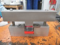
I think I may need a few saddles so I made a former for them.
P1030136.JPG

If the GN ignitions prove to be unreliable at least I now have a working trigger system that could be used with an Ignitech programmable unit, but the idea for me was to make a cheap reliable system that we can use on our sidecars.
 
I think I saw some fluffy advancing initially, but I hope I remember correctly it is the ignition learning what to do. It did appear to settle down.
Yes, the first one I tried did that. Would settle down after 10-20 seconds. Otherwise worked fine.
Are those stainless screws on the rotors outer 4 holes?
 
Thanks for confirming my thoughts Jim. Yes I started to put stainless screws in the rotor but stopped as the it is for a total loss system and will not have the field energised.
 
Back
Top