Stuff my dog says; on second thought I'll just build a race car

Well, really digging into steering now and I've come to realize that what I was planning simply isn't going to work. I was planning on a Chevy Vega steering gear with the Pitman arm mounted backwards, a center link and tie rods. The Pitman arm would be moving in an arc the opposite direction of the steering arm on the spindles though and it's just gonna put everything in a bind when going out to full steering lock. Going rack and pinion seems like a necessity, due to the cramped nature of the nose of the car there just won't be enough room to move a steering gear forward to even the steering geometry out. The size of the universal steering racks I'm finding also don't work for direct links either but I do have a plan for that.

Elaboration later.
 
So I'm looking at things and the distance between the tie rod pick up points is 45 inches, my lower control arms are ten inches each and the tie rods need to be close to that same length if they're going be down by the lower ball joint. The universal steering racks that I can find are either Mustang 2 racks which are 41 inches wide or Thunderbird racks which are 45 inches wide. Some of those lengths are inner tie rods, but it's like 5-7 inches ish. Part of the fun is that I was looking at steering racks on Summit/Amazon/Jegs/Speedway and the like and none of those place actually have comprehensive measurements of their racks. My five to seven inches is based upon looking at the pictures and going "Um I think this is probably about that".

I really dislike the lack of information regarding stuff like this. Give you total length and the length of the input shaft, but neither of those are really relevant to someone in my situation. I want distance between the pickup points for the tie rods, the ratio of the rack or the number of turns lock to lock with the total overall travel of the rack. Everything else are things I can work with pretty much regardless but those are all the things that are designed into the steering rack and I can't change those. Of course they give you the information I don't actually need, I kinda understand though because what they do give you is the kind of info you need if you're replacing the rack in an already existing vehicle.

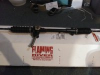
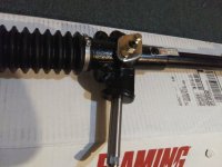
Looking through things this sitting here now I have found a Cobra/MGB rack on Flaming River's website that seems like it would be really good for what I'm doing. The distance between the joints is 24 inches, so to get 10 inch tie rods I simply move the pickup points on the spindles a half in inboard from the ball joint. It's three turns lock to lock which is exactly what I'm looking for, and a 6.25 inch overall travel. It's also two and a half times more money than the other stuff I was looking at last night and I seriously dislike Flaming River products. I may have to swallow the cost and the dislike though, and to be fair most of the issue's I've had with Flaming River stuff in the past won't apply to this situation.

Also I ordered some high angle Heim joints last night from Ebay to use as ball joints so I could measure them and draw the spindles. Need me some money....
 
You know what nobody talks about? How much the front wheels of a car actually turn at full lock. I did the old eyeball test on my Expedition the other night and it looks close to 45 degrees, but I don't recall ever having seen an actual number for total steering angle at the wheel. I spent about 10 hours today looking at steering and eventually got some where I think.

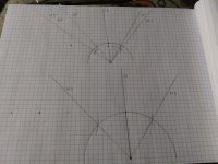
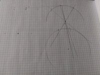
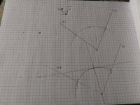
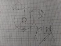
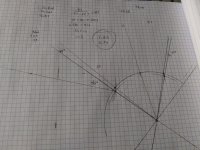
Nobody talks about Ackermann Angle either it seems. It's one of those things that is just sort of accepted, and it sounds logical the front wheels having to turn differing degrees in order to smoothly go around a corner. Looking around I eventually found an explanation for how to find the number needed that was easy enough to understand. If you're looking straight down on the spindle, the imaginary line from the ball joint through the steering connection should line up dead smack through the center of the rear axle. That sounds easy enough but getting it to actually work proved very difficult. I've now got pages and pages of useless trial and error.
20210213_142151_HDR.jpg 20210213_142201_HDR.jpg 20210213_142217_HDR.jpg 20210212_212601_HDR.jpg

The problem I kept running in to was trying to get that angle through the rear axle correct in a way that's actually able to be produced. It's gonna be exceptionally difficult for me to get accuracy down to the ten thousandths of an inch. Trying to get the tie rod to actually work proved difficult too. I kept running in to a problem of the inner and outer tie rods moving so far as to not be able to stay connected. Lastly total steering angle took a lot of trying to get something that felt right. Even with the known values of the Cobra rack it's trying to line up the distance of the steering arm to get a usable amount of steering angle with the initial Ackermann angle on the spindle. After screwing around a while and making several dumb mistakes I eventually settled on some numbers.
20210213_212930_HDR.jpg
The steering link needs to be 5.75 inches behind and 1.25 inches inside the lower ball joint. This leaves me with a tie rod of 10.25 inches and that point described by the Ackermann is slightly in front of the rear axle but still quite close. Reading it was said that having more than is necessary is desirable for low speed tight turns while having less is desirable for lots of high speed cornering. I still think it's far more likely to auto cross this thing than do legitimate track days, so it should be OK slightly high. Total steering with that set up ends up 41 degrees on the inside tire and 31 on the outside tire. These with the wheel base and track width should have the center of the car doing a 33 foot diameter circle at full lock which sounds about right.

I still need to do the numbers and see where it all needs to be vertically in relation to the lower ball joint to work the bump steer how I want it but it's been a day and I'm done. While I was doing numbers I decided to actually mathematically find the roll center and it's 3.3xx, I'm just going to leave it at that, too many issues encountered trying to move it. Gonna go in to work tomorrow and probably make a block off plate for the fuel pump since it'll be running an electric pump with the fuel cell and cut down that slide collar from the transfer case.
 
A further word on desirable bump steer this morning. As you turn the vehicle at speed there is always going to be some level of slip angle to the front tires as grip is never absolute. The forces acting here are related to speed so the assumption is that with the front tires at a given angle the actual turning radius increases as velocity around the circle increases. Since the turning radius is increasing you want the steering angle to lessen progressively with speed as well. My thinking is that if you attach this to the body roll of the vehicle, which in theory is also related to the amount of lateral force and therefor slip angle, you can use bump steer to do this change of the steering angle independent of any steering wheel input.

The outside tire is where the bulk of the cornering force takes place and it's going to be under compression so the idea is that as the suspension compresses bump steer should cause that wheel to toe out slightly, the inside tire will be unloading and will need to toe in. The bad news is I have zero idea of actual numbers to go with this. I'm not fancy enough to know what the coefficient of friction of my tires is, nor do i know the center of gravity of the vehicle or the stiffness of the springs or the weight of the vehicle. That means I can't put numbers to the amount of suspension movement under cornering load, nor do I know the amount of load that will be encountered on cornering. So wild ass guessing will occur.

One thing I have going for me is the load on the vehicle should stay the same. Realistically the fact that this is a single seat race car makes this entire process exponentially easier. I can put the vertical loads on the chassis in one place and never have to worry about them moving. There won't be luggage to think about, the fuel tank is going to be along the center axis of the car to fuel load won't change the side to side weight balance. I don't have to contend with pot holes or the presence of size of passengers. Tire wear really isn't a concern either so I can set the thing up with extreme alignment angles. People often talk about wanting a race car for the road, but the two things are so different from each other that you can't have a vehicle that works equally well on road and track, there would have to be compromise after compromise.
 
Well, I went in to work today but wanted to get some actual paid stuff done first. So I did that then looked outside and saw the freezing rain had started early and that sent me packing so nothing actually got done today but it wasn't because I was lazy this time.
 
20210219_131935_HDR.jpg 20210219_131938_HDR.jpg

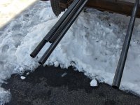
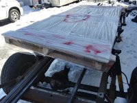
I got metal, which shocked the heck out of us today. We didn't think the place would be open much less actually try to deliver today. Talking to the driver he said they told him to just go where he could and ignore the rest for now and he decided to come to us because he likes to look around and see what we've got in the shop. He almost didn't make it up the driveway, even days later it's pretty much just all packed sleet and ice.

The plan was to have it delivered to work since that's where we are and then fork lift it across the street to the play shop. That's clearly not in the cards with the forklift and we don't feel like carrying 300 pounds of steel down a short hill and across the street with ice everywhere so it's staying where it lays for the weekend. So next weekend start building the chassis, go in Sunday and do those things I didn't get a chance to do last Sunday.
 
I made a big pile of metal tonight.
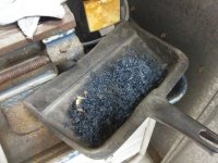
20210224_193553_HDR.jpg
I ended up not feeling well Sunday so I stayed home and looked up parts to have going forward. Been staying after messing with it this week, made the plate to cover the fuel pump hole Monday.
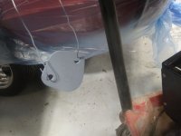
20210222_184243_HDR.jpg
Also took the transfer case slider and used the plasma cutter to cut the gear teeth off it.
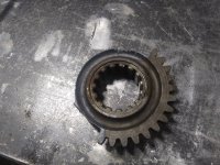
20210222_184304_HDR.jpg
I'm not sure if I'm shocked at how well the plasma cutter went through the gear, or if I shocked at how easily the plasma cutter went through the gear......

Tuesday I was planning on getting more done, and I kinda did. All I got accomplished though was putting the block off on the engine. One of the guys asked if I had made it or bought it, then said it was probably impossible to buy something like that for the Tornado. Pretty much all those engines back in the day used the same fuel pump style though and this one is no exception. I'm just cheap. Then we went back and did a shop planning session for the Gladiator build that lasted until 7:45 so I got nothing else done.

Tonight I got to actually work some more though. Took a grinding stone and cut the gear down a little with it to get passed where the plasma cutter hardened the steel and then chucked the gear up in our lathe.
20210224_193546_HDR.jpg

I know nothing about this other than it was used and it's at least twice as old as I am. We've had the thing in the shop for a few years now and I think this was the first time we've done something useful with it. There is another smaller one that we use fairly often and runs off 110V rather than the 220V the big one uses and is on a cart so it can go to where you're working. The big one is in the corner across the shop from the nearest 220V plug right now and weighs hundreds of pounds so it's just too inconvenient most times. Worked great for this though.
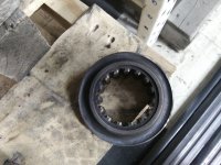
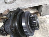
20210224_193630_HDR.jpg 20210224_193618_HDR.jpg
So now that's turned down and nice and smooth. I did notice an issue Monday when I started messing with it though in that the piece of pipe I thought I was going to be able to commandeer from work is like 1/16 of an inch too small in diameter so I need to buy a piece of 6 inch pipe. 6 inch was what I was thinking it needed back when I first measured everything but saw we had that random piece of 5.5 inch and was hoping to be able to use it, because again I'm cheap. Was hoping we'd get started bending tubes and welding on a chassis this weekend but apparently we all got volunteered into working Saturday.
 
I seems unusual to me that a plasma cutter will harden the metal?? A couple of months ago I had two 1/2" thick discs that had been cut with plasma. When I tried to turn them down a little on the lathe I could not cut them without wearing out my HSS tool bit. Perhaps this is because the plasma gets the metal near the cut exceptionally hot momentarily and then the bulk metal cools it rapidly??

Good to see construction is progressing...:)
 
I seems unusual to me that a plasma cutter will harden the metal?? A couple of months ago I had two 1/2" thick discs that had been cut with plasma. When I tried to turn them down a little on the lathe I could not cut them without wearing out my HSS tool bit. Perhaps this is because the plasma gets the metal near the cut exceptionally hot momentarily and then the bulk metal cools it rapidly??

I have no idea the mechanism by which it does it, really I can't even say 100% that it does happen. Anecdotal evidence suggests it does, like you said the metal seems like it doesn't cut or sand the same after it's had the plasma cutter near it. It's something that I've always heard others say too. Even in this case I could tell a difference on the lathe with the portions that I didn't get sanded away from the plasma cut edge to the portions that I did. I had a dull bit on the lathe anyway and you could feel the thing bucking a little bit when it hit those hardened bits on the edge.
 
A plasma torch uses compressed air for cutting. Air is a tad under 80% nitrogen. So in effect, you're doing a poor mans job of nitriding the cut edge. So yeah... a very thin layer of the cut will be harder than the parent metal.
 
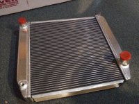
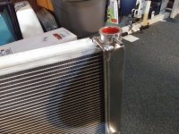
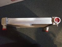
Got more stuff ordered this afternoon. Ordered the other three wheels, a radiator, a steering rack, and collectors for the headers. Unfortunately haven't done anything as far as actually building the car. We're working six day weeks now trying to push cars out by May, which hasn't left any time to get the frame built. The plus side of things is the weather is getting nicer and I've been able to ride back to work after lunch the last couple days.
 
The axle I grabbed from the Wagoneer has been sitting in the parking lot since my son and I messed with it a few weeks back and has been leaking out the pinion seal. Probably a result of the anti-rust soaking I gave it. I got a new pinion seal and cover gasket for it this morning and took some stuff off it after work tonight and found out my pinion yoke is junk. It looks like it's had a U joint or strap break at some point and it's beaten a small chunk out of the yoke. Digging in further I'm guessing that broke during a one wheel burn out.
At some point an owner of the Wagoneer loved them some one wheel burn outs. The ring and pinion looks OK, and even with the state of that thing and looking like it'd been immobile since the Carter administration, there isn't really any rust inside the differential. What it does have is a pair of worn out spider gears and their associated shims. Very likely the cross shaft is toast as well. I can't feel any movement cross shaft to carrier though so at least that's presumably in good shape.

The good news is that a coworker has a Dana 44 front axle laying around that someone cut a knuckle off intending to narrow it. The ring and pinion would obviously be different being a front axle, but I'm thinking the carrier and everything in it should be identical. The yoke I'm even less sure about, I could see it having a different spline pattern but hopefully I can use it too.
 
I dunno man. Seems like the effect of plasma torches on somebody's Wagoneer that's been sitting since the Mayflower
 
Last edited:
Also saw Pitman arm on the sole surviving Vega is now turned backwards or something
 
Also saw Pitman arm on the sole surviving Vega is now turned backwards or something

Read more? Or less really if this bothers you? The axle is from the Wagoneer which is a leaf spring rear suspension, it's being modified to fit in the race car I'm trying to build which is coil spring and therefor doesn't need those perches. The Vega talk was trying to decide how to run the steering on the race car. Vega steering gears are a super popular way to do steering on early hot rods and they are reproduced in bunches for that purpose. I have since realized that it needs to be rack and pinion steering and have a steering rack being delivered today.

Paul hit the nail on the head with his description of the thread. Once I started the race car idea this thread turned into a chronicle of all the decisions, problems, and details that go into a project like this (which is a huge under taking).
 
Back
Top