As long as one condenser lead goes to each coil lead it's golden.
-
Enjoy XS650.com? Consider making a donation to help support the site.
XS650.com receives a small share of sales from some links on this page, but direct donations have a much greater impact on keeping this site going.
You are using an out of date browser. It may not display this or other websites correctly.
You should upgrade or use an alternative browser.
You should upgrade or use an alternative browser.
some wiring diagrams
- Thread starter inxs
- Start date
-
- Tags
- diagram electrical wiring
340frontporch
Grandpa Butterfly
that confused me... one condenser lead per coil correct?
Yes, one condeser lead to one coil lead.
SwamiJ
The Pres.
I just salvaged a 1980 xs650 from a farmer who had it stitting in a barn and this is my first go around with this set up and was wondering was is the most down and dirty way to run the elictrical to see if this thing will fire before i start replaceing stuff. I dont need light or anything to work just the engine to run. Any help?
I just salvaged a 1980 xs650 from a farmer who had it stitting in a barn and this is my first go around with this set up and was wondering was is the most down and dirty way to run the elictrical to see if this thing will fire before i start replaceing stuff. I dont need light or anything to work just the engine to run. Any help?
Dont flash her up with out dumping oil and replacing sump and oil pump filters!
SwamiJ
The Pres.
Dont flash her up with out dumping oil and replacing sump and oil pump filters!
I got that under control. Im not to shabby with the mechanical but the wiring always seems to give me the run around
340frontporch
Grandpa Butterfly
on the coils, (stock) does it matter which terminal is from the condensor/points and which is from the ignition? i'm running my ignition straight from the keyswitch to the coil. bike will not start, engine was torn down (top end) and am getting compression (not sure how much). donna check to make sure of ignition to the plugs.... wanna make sure i didn't do something stupid on wiring as that's the only thing i can think of at the moment.
on the coils power flows from your switch to the coils, then to the points and condensers.
chilliwackwestie
XS650 New Member
- Messages
- 3
- Reaction score
- 0
- Points
- 1
Hey;
this site is awesome I must thank all of those who put in the time and effort to design and post these diagrams. It has really helped my dumb-ass. I found a link on motorcycle wiring theory thought it might help some of u guys out.
http://www.btinternet.com/~jhpart/bkwirec.htm
cheers
Glen
this site is awesome I must thank all of those who put in the time and effort to design and post these diagrams. It has really helped my dumb-ass. I found a link on motorcycle wiring theory thought it might help some of u guys out.
http://www.btinternet.com/~jhpart/bkwirec.htm
cheers
Glen
I have a 1975 XS650B that someone has changed to electronic ignition from an 1981 or 82 XS650 Special. I have no idea if all the wires are connected in the right place,I've looked at the diagrams but don't see anything that matches this mess.Any Help out there on this.thanks Dan I'm in Glendale,AZ
motodangt, First off let me say welcome to the board.
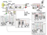
Next, To make it run you need power to flow from the battery to the 20 amp fuse on a red wire to the key switch. From the key switch on the brown wire to the kill switch. From the kill switch on the yellow wire. This yellow wire hooks to a red/white wire that goes over to the stock 75 coils. It should have a two wire plug. This is where you need to hook the red/white wire from the TCI box and the red /white wire of the coil.
The pickup on the stator should plug into the TCI box on matching colored wires. The orange wire from the TCI box should hook to the orange coil wire. The TCI black wire to ground.
The TCI boxes for 81 and 82 are different. The way I mentioned is for the 80-81 TCI box The 82 TCI box has 7 wires. An extra black/white wire, cap it off. This should get the bike to fire the plugs and make it run.
If the wiring is a real mess I would stake it all out and start from scratch.
This diagram, thanks Jayel, shows how to wire your bike with the parts you have. After the kill switch you hook in the TCI box and coil just as it shows.
Wiring can be a bit scary at first. It gets easier as you go.
Attachments
Last edited:
jimmy5090
XS650 Addict
i dont get what the power outlet is that is on the simplified 81 diagram. alfredo and grinder discussed it on page 4 but not real clear about it. on the diagram it shows pwr outlet and looks to be a ground can someone explain this for me? pics?
Jimmy5090, The power outlet is a place to plug in a battery charger or accessories. Like heated gloves. You don't have to have one.
Quite often when you get a motorcycle battery charger comes with the cord ending in a two prong plug. They have two sets of ends that plug in the cord, a set of clamps like any charger has and a set of leads that you can permanently attach to the battery. That way you can have the plug end where you can get to it and just plug the charger in. This saves taking a seat off or some other sort of inconvenience.
If you have more than one bike you can get extra sets of leads so you can plug in the charger on all your bikes.
jimmy5090
XS650 Addict
sweet thanks for the quick response. you think i would know what they where talking about when i have one on my cbr600. sweet now i can get to wiring thanks to all you guys and the wiring diagrams. without this thread i would be completely lost.
jimmy5090
XS650 Addict
on the 81 simplified diagram the alternator only has 3 white 1 black and 1 yellow capped what do you do with the red? cap and also my alternator has a green instead of a black i am assuming that should hook to the black on the reg/rec? my alt also had a blue?
Ok, On most diagrams they show how things are electrically. How they are physically is often quite different. In this diagram it does show a black wire from the alternator to ground. This is to show a ground path for the alternator. On the bike there isn't a black wire, it grounds thru the alternator housing to the engine case and then to the frame.
On your alternator if you trace the wire bundle out the rear of the alternator and up to the 6 wire plug. You will find 3 white wires, a brown wire, the one you think is red, a green wire, a blue wire.
The yellow wire is in it's own single wire plug. On the stock wiring it hooked to the safety relay. If you want you can cap it off, If youuse the safety relay hook it to the relay.
The blue wire is for the neutral light. The other end of the bule wire comes out of the wire bundle and goes over to hook to the neutral switch. From the 6 wire plug it hooks to one side of the neutral light, then a brown wire hooks the light to the brown wire after the switch. This way when the key is on power flows out the brown wire to the neutral light, from the light on the bule wire to the neutral switch. When in neutral the switch makes contact and grounds the bule wire to the engine. This makes the neutral light light up.
At the 6 wire plug the 3 white wires hook to the 3 whites from the reg/rec.
The brown and green wires come from the brushes. The brown hooks to the brown wire from the reg/rec and from there up to power after the switch. The green wire to the green wire of the reg/rec. The black wire from the reg/rec to a frame ground. I like to hook another wire from where you ground the reg/rec black wire up to the same place you hook the battery groung.
The red wire from the reg/rec goes up to hook in between the swtich and main fuse to charge the battery.
jimmy5090
XS650 Addict
sweet thanks xsleo i think i got it
A question - I'm working with the 2nd diagram on the 1st page of this thread.
http://i957.photobucket.com/albums/ae54/inxs-de/wiring/650wiringchoppervh0.jpg
I'm confused because this diagram shows the white/red wire coming off the elec ignition going to the coil (as most of the other diagrams have too) but then it also ties that red/white wire into the brown wire that comes off the rectifier. Brown wire from brushes on alternator also hooks into the brown wire from rectifier. Then that wire eventually gets power from the ignition switch.
I guess I'm confused because other diagrams just show that red/white wire just going from ignition to the coil, and not tieing into the brown wire.
Am trying to see this as a whole, but am wanting to make sure I know if this is correct or not before I connect power for the first time.
(I don't want to fry anything)
thanks!
Last edited:
Em, after staring at those diagrams for way too long.. I think it got figured out. Most of the diagrams show the power wire coming into the TCI as just red. The diagram you're talking about is more correct because the wire is mostly red with a white stripe and they call it R/W like the factory diagrams.. Anyway I guess when comparing that to the other diagrams, think of the R/W as just red. Most diagrams show that red wire going to a kill switch then to the brown wire for power. The diagram you posted doesn't have a kill switch so that's why it just runs right into the brown wire.
Em, after staring at those diagrams for way too long.. I think it got figured out. Most of the diagrams show the power wire coming into the TCI as just red. The diagram you're talking about is more correct because the wire is mostly red with a white stripe and they call it R/W like the factory diagrams.. Anyway I guess when comparing that to the other diagrams, think of the R/W as just red. Most diagrams show that red wire going to a kill switch then to the brown wire for power. The diagram you posted doesn't have a kill switch so that's why it just runs right into the brown wire.
hi Travis, thanks for the response and taking the time to check it out. Much appreciated.
On mine, that wire is actually mostly white - almost just like a candy cane.
Similar threads
- Replies
- 2
- Views
- 125