Why is the PAMCO better than points?

Pete P, I always apprecitate an opportunity to expand my understanding, which is rather elemental. So thank you for your comments.

But I think our differences here are sematic.

My simple understanding is that the voltage input to the primary windings of a coil in the points bikes (stock/no ballast resitor) is identical to the input to the primary windings of the coil in a PAMCO equipped bike.

The PAMCO allows for a coil with lower resistence primary windings than points can handle without arcing and that lower resistance coil puts out a hotter spark than the higher resistence coils used on the points bikes.

I phrase that simply as "the performance advantage is from the hotter coil"

So, unless of course you are saying that the PAMCO would result in a hotter spark from the same coil, our disagreement is a matter of word choice.
 
But it is true Gentleman. I don't know why you think it isn't. So since I'm the retired Automotive and Electronics instructor, you prove to me it isn't.
 
Burns . . if the circuit contains no ballast resistance, then what you are saying would be true if using the same coil. Buy using a coil of less resistance, then you will have a stronger primary circuit. However, if you used that low resistance coil with a points system, the points would not last long. There is where the advantage would be in using an electronic ignition; you could run the lower resistance safely.
 
Burns . . if the circuit contains no ballast resistance, then what you are saying would be true if using the same coil. Buy using a coil of less resistance, then you will have a stronger primary circuit. However, if you used that low resistance coil with a points system, the points would not last long. There is where the advantage would be in using an electronic ignition; you could run the lower resistance safely.

I think that you are adding to rather than disagreeing with what I am saying.

You would agree, I believe, with this statement : It is the lower resistence coil that the PAMCO permits that gives the performance improvement
 
But it is true Gentleman. I don't know why you think it isn't. So since I'm the retired Automotive and Electronics instructor, you prove to me it isn't.

PetesPonies;

You clearly stated that in a points system the ignition coil can not have more tham 9 volts across it. Are you still saying that is true?

Take a piece of paper and draw a simple circuit. Battery positive at one end, a line from the battery + to the ignition coil; another line from the other end of the coil to the points, and from the points to a ground connection (battery -). Assume the battery voltage is 13 volts; now if you say the coil has only 9 volts, please explain where the other 4 volts went to.
 
Bingo Burns, yes I agree. And again as I started this with . . . I wasn't talking specifically of the Pamco, because I do not know how that ignition specifically works. I was just speaking of electronic ignitions in general. But alas . . we are in agreement :)
 
PetesPonies;

I asked this question earlier, but I don't see your response yet. I'm asking the same question again, so that this thread is not left hanging.

You clearly stated that in a points system the ignition coil can not have more tham 9 volts across it. Are you still saying that is true?

Take a piece of paper and draw a simple circuit. Battery positive at one end, a line from the battery + to the ignition coil; another line from the other end of the coil to the points, and from the points to a ground connection (battery -). Assume the battery voltage is 13 volts; now if you say the coil has only 9 volts, please explain where the other 4 volts went to.
 
I ABSOLUTELY did not say the "ignition coil" cannot support more than 9 volts. I said the points cannot survive with more voltage than that going across them. For longevity, they are kept in that range or less. It's a very very basic fact. Look to early transistorized ignition systems and see why they were incorporating a transistor into the circuit. See what their goal was and why they felt it was needed. Transistorized ignitions were precursors to the electronic ignition we have had for the last 35 years or so.Why do you think the amount of resistance in the primary circuit is so critical?? Because the resistance sets the final voltage. If you have an old car that still has points . . . turn the ignition on and with the points closed , measure the voltage in the primary circuit.
 
PetesPonies;

Well here is your quote "Primarty voltage on a points syste, ( doesn't matter if its a bike or a car ) is going to be from 6-9V max."

I have used points on my XS650. When I measured the voltage across the ignition coil primary with points closed, I measured 11.4 volts, with the battery at 12.0 volts. (0.6 voltage drop across the main fuse/ignition fuse/ignition switch/kill switch.)

Also, resistance does not set the final voltage. Voltage of the primary winding is the voltage from the alternator/battery output, less the small voltage drop across the fuses/ignition switch/kill switch. Resistance sets the current flow.
 
Listen retired, you are just fixed on not believing me. Why?? And I'm not specifically talking about the Yamaha. I'm talking about ignition systems in general. But you are saying things that are contrary to basic electronics. When I say the resistance sets the voltage . of course it does. The voltage is divided in a DC circuit based on the the total resistances and where they are individually. Its basic electricity. I'm not going through an electronic course with you. These are basic things. I know what I'm talking about and at this point I'm tiring from your lack of interest in learning or reading what you need to carry this on. It's just the facts . . plain and simple. Go read some info on electronics, DC series circuits would be a good place. Then carry that to a basic ignition chapter and we can continuue this at a later time. Here's a start, its on voltages and how they are divided. Enjoy.

http://www.allaboutcircuits.com/vol_1/chpt_1/6.html
 
Last edited:
Well I'll agree ya'll disagree.
I'm sure each of you have formal training or at least express yourselves as having knowledge.
And each seems to have practical experience.
You are way beyond most folks ability to comprehend or care to learn.
I'm going to ask each to pull your horns in and move on to threads where your knowledge can help.Maybe like this one.
http://www.xs650.com/forum/showthread.php?t=20928
Or at least take it to pm's.
But I'm just one forum member so feel free to tell me to stuff myself.
Then maybe the 3 of you can get it out of your systems.
 
Listen retired, you are just fixed on not believing me. Why?? And I'm not specifically talking about the Yamaha. I'm talking about ignition systems in general. But you are saying things that are contrary to basic electronics. When I say the resistance sets the voltage . of course it does. The voltage is divided in a DC circuit based on the the total resistances and where they are individually. Its basic electricity. I'm not going through an electronic course with you. These are basic things. I know what I'm talking about and at this point I'm tiring from your lack of interest in learning or reading what you need to carry this on. It's just the facts . . plain and simple. Go read some info on electronics, DC series circuits would be a good place. Then carry that to a basic ignition chapter and we can continuue this at a later time. Here's a start, its on voltages and how they are divided. Enjoy.

http://www.allaboutcircuits.com/vol_1/chpt_1/6.html

PetesPonies;

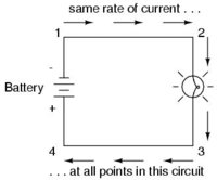
That's an excellent link (allaboutcircuits) to demonstrate exactly what I (and 2 other posters) have been saying. The diagram from your link shows a light bulb ( a resistance)............just let the light bulb represent an ignition coil. The quote from the link as stated below, seems to say that the full battery voltage will appear across the resistance. In other words, if the battery voltage is 13 volts, you cannot have only 6 to 9 volts across the single resistance as you have tried to convince us.

"The voltage between points 1 and 4, of course, will be the full amount of "force" offered by the battery, which will be only slightly greater than the voltage across the lamp (between points 2 and 3)."
 

Attachments

  • 00030.JPG
    00030.JPG
    11.2 KB · Views: 152
and in this vain, here is a great example page. Work through it. Anyone can do it. This is very similar to some simple worksheets I used to use with my students.

http://www.wisc-online.com/objects/ViewObject.aspx?ID=DCE3402

over and out . I promise :)

Another good link Peter. Yes, the voltage divider rule is a useful tool.

However in the simple ignition circuit that we have been talking about for 3 pages, there is only 1 resistance, but the rule still applies.

Example: 13 volt alternator/battery used with a 4.5 ohm ignition coil. Let the voltage across the ignition coil = V x

therefor Vx = Rx / Rt times Vt

Vx = 4.5/4.5 times 13

Vx = 1 times 13

Vx = 13 volts

Again Peter, this shows that the entire supply voltage is dropped across the single resistance (coil) in the circuit.
QED
 
hi guys well with pamco ... 14-0901 you get everything ,,, instal as petes drawing show ,,,, check it ans forget it runs superb ,,,,, even new bikes get upgrades ,,,we are just upgrading a 30year old bike enjoy it regards oldbiker
 
Well I'll agree ya'll disagree.
I'm sure each of you have formal training or at least express yourselves as having knowledge.
And each seems to have practical experience.
You are way beyond most folks ability to comprehend or care to learn.
I'm going to ask each to pull your horns in and move on to threads where your knowledge can help.Maybe like this one.
http://www.xs650.com/forum/showthread.php?t=20928
Or at least take it to pm's.
But I'm just one forum member so feel free to tell me to stuff myself.
Then maybe the 3 of you can get it out of your systems.

3? Hey dude, I got a "bingo" (agreement reached) No horns here pod-nah.
 
There is resistance everywhere. Voltage "divides out" everywhere. Wiring has resistance and each coil contains a specific amount. I'm betting you did not do what I asked you to do several days ago. But to MY point, you seem to be ignoring. I AM NOT ( have said this several times ) speaking to a XS650 ignition system. I AM speaking to a general points type ignition. If you find fault ( you can't because I am talking about the truth ) in my statements in regards to the way a points ignition operates, then show me where; specifically. I laugh with each post, because I'm right. Its seems silly to continue saying it, but . . it's the only thing I can say. I guess you are standing on a specific term or something I'm saying which you think is wrong??? I don't know. Here is an easy ( for everyone ) example of why or how the voltage is controlled on MOST points ignitions. Look at a typical Ford starter solenoid. You find them on Harleys as well as boats, etc. The Ford design solenoid is used a lot in the industry ( or was used ). When the ignition switch ( key ) is turned to start, full ( typically 12.6 V ) is sent to the ignition system via a terminal on the solenoid. When you release the key, that terminal is no longer hot and the full voltage is interrupted. Now power to the ignition system, ( read that primary ignition circuit ) is supplied through the resistance circuit. The resistance circuit feeds the primary winding of the coil. Check the voltage there, its not full. It may be controlled by a ballast resistor or a resistance wire; same effect. Now why do they go to all that trouble if full voltage could be used at all times?? What they are doing is allowing full voltage momentarily to help with starting, then cutting it back to 8-9V for normal running. Many engines have done this. If XS650s don't . then OK. But it's more prevalent than not, I PROMISE you that. I am ignorant of many things, I like to learn. I'm open to learning lots of things . . but I'm right here :banghead: I'm tired, let's move on. Even in class I would have to say . . see me after class, we need to move on.
 
PetesPonies;

A disagreement has occurred because I was talking about XS650 points type ignitions.You were talking about automotive points type ignitions.

This forum is about XS650's and the specific question was about XS650 ignitions. I was giving information directed at the specific question. You started talking automotive ignitions which caused confusion, because they are not the same as the XS650.

Yes, you are correct that some automotive ignition coils only have 6 to 9 volts, if they use a series connected ballast resistance. I even mentioned automotive ballast resistance was used in the old days with chysler as an example.

Just to be clear, the stock XS650 points type ignition did not use the automotive design of having a series ballast resistance in the coil primary circuit.

I am familiar with the reduced current required for a points system. I have used an Accel ignition coil (3.3 ohm primary) with a Pamco for the last 4 years. However, I also used the stock OEM points wih the Accel coil the first year I ran the bike back in 2007. I used a 1.3 ohm ballast resistor in series with the coil primary, to limit the current flow, to protect the points from burning.
:bike:
 
+1 for RG's composure. PP- you should re-read your posts, b/c they come off as condescending, which I hope isn't intentional.

Both of you clearly have deep knowledge of these ignitions, so thanks for the tutorials.
C2
 
Back
Top