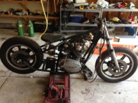
So I am ready to slim down and rewire my 1980 hard tail this month. After this weeks inspection in NY I was able to pass without blinkers so that sparked the thought of reducing the loom. Since wiring is the last avenue I must travel down on this bike I just have a few questions that I'm sure will be easily answered, but I still have to ask. Keep in mind if you decide to respond I would like to keep the electric start as well as the kick start, I will have a full sized battery and I do not plan on running a PMA kit. Also I'm comfortable adding neutral, high beam and speedo metering lights so no worries there...
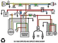
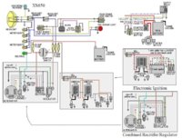
On the diagram below it says 1981 but I'm certain 99% of this looks the same as my 1980 special. The questions I have are these:
1. The blue/white from the starter solenoid goes to a starter switch, correct?
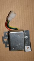
2. Are the two relays pictured below needed? I'm fairly certain the round is blinker relay/cancel and can be removed but unsure about the square one.
3. I assume lighting reserve is coming off. Will it affect the headlight, dimming etc.
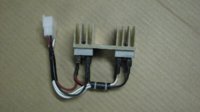
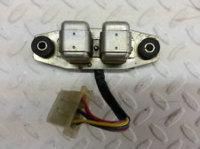
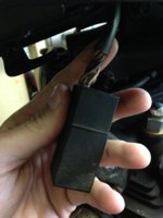
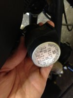
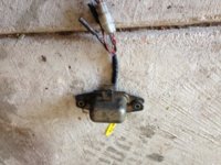
4. There is a gold "device" that is hidden in a fake oil bag right now that seems to house two relays. I believe it is a safety relay but I don't see it on the wiring diagram anywhere nor do I have any safety switches on the kickstand or anything. Is it important for shutting of the starter?? Please advise.
5. From the battery it shows a "Power Outlet" stupid as this may sound...What is that and where do I hook it up? Does this literally mean a place to plug my phone charger up to? Because I don't see it on any other diagram.

(EDIT: found that this is just an outlet as I thought sorry)
I have already switched to blade fuses and I have a good idea of what I want to do but any advise on these questions would be greatly appreciated. I don't want to miss something, have the bike fire at home, them drive somewhere and realize it didn't charge correctly or something crazy like that.
Thanks in advance for any help guys/gals.