CoronaXS
XS650 Member
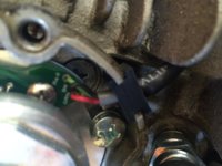
So I just finished installing my pamco ignition. I have no spark whatsoever. I noticed that the sensor itself seems to be wired incorrectly. The three leads soldered into the board on the sensor are red green and black. The board is also labeled this way. BUT the red and green are reversed. Can this be my problem? I know polarity doesn't matter at the coil but one lead (red) is tied into ignition and the other (green) isn't. Also I'm unsure if this can cause a problem at the advancer unit. Pete! Help!!
Also, could someone help me verify the orientation of the advancer board? I want to double check that I didn't put the cap on backwards and wire it backwards!! I just need to know what to look for on the actual board to know what side is coil and sensor.
Posted via Mobile
Also, could someone help me verify the orientation of the advancer board? I want to double check that I didn't put the cap on backwards and wire it backwards!! I just need to know what to look for on the actual board to know what side is coil and sensor.
Posted via Mobile
Attachments
Last edited:

 I removed the block that ties in the locating pin to test the sensor with out cranking it over. I get .4V on the green wire on the sensor when the magnet passes over but 0 going to the coil on the other side of the advancer. Do I have a bad advancer? I'll be testing the coil next. Thanks for the help Pete.