New member and first xs650.... with charging/wiring issues

starguymike

XS650 Member
Messages
17
Reaction score
0
Points
1
Location
Cullman, Alabama
Just wanted to say Hi and post a few pics of my new to me mostly 1979 xs650. I have been lurking for awhile and realize there are some on here that probably won't like my bike. I got a great deal on it though and it is fun to ride. I have been through alot of info in the electrical section and I am still pretty confused i guess. I believe I have a regulator/rectifier from a 80+ bike. PO made a pretty big mess of the wires, I will clean them as soon as I figure out where they actually go. I have spent the last 2 days trying to solve my charging problem as cheaply as possible. As it stands now I am going to post pics and hopefully someone will ask questions for stuff I have checked and maybe step by step we can figure it out. It would be greatly appreciated. I have already decided that if it is a stator or rotor problem I will likely just hold off and get a PMA, but if it might just be my wiring or the reg/rec I may fix what i have. ***I have read Curlys guide but between the 2 different years its leaving me dumbfounded. I believe I have it wired correctly but don't know how to troubleshoot the individual parts, and also most schematics mention a black wire coming from the stator bundle But i do not have one***Also I noticed all of the nylon screws are not there and something else looks strange about the brush area but I can't place it, I am not for sure if the PO did the nylon stuff the right in the first place :banghead: I will be getting the nylon screws asap. I realize it will not actually charge without them. But I was hoping everything else could be tested or verified to be working as much as possible.Thanks for taking the time to help guide a new guy, sorry this ended up so long.

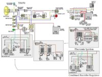
1979 xs650 with a solid state reg/rec
toggle switch to flip and kickstart only
only other electronics are the headlight, tail light, and brake light..I have these under control.
Tests so far=Slap Test Failed but the bolt seems to have residual magnetism left,
either brush to ground produces~25VAC, white to white from stator produces only .1VAC. tried to ground the green to test regulator and blew a fuse that was sending voltage to the reg/rec and to top brush??(nylon screw missing maybe)
IMG_0192.JPG
IMG_0190.JPG
IMG_0191.JPG
 
Last edited:
Welcome to the forum, starguymike.

Yep, quite a mess you've got there. These bikes have two basically different types of alternators. Almost indistinguishable, you've got to get in there to see which type.

The early 70-79 models have a regulator that supplies power to the rotor thru a carbon brush, the other brush is grounded.

The later 80-83 models have a regulator that grounds the rotor thru a carbon brush, the other brush is powered by the bike's 12v system.

Then, there's the frankenbikes, modified and intermixed parts. Nylon screws show up here, to isolate the grounded brush on an early alternator so that it can use a later regulator.

These threads have more info and pics that may help:

http://www.xs650.com/forum/showthread.php?t=38428&highlight=brushes
http://www.xs650.com/forum/showthread.php?t=40260&highlight=brushes
http://www.xs650.com/forum/showthread.php?t=41778&highlight=brushes
 
Thanks so much for the response. After looking at those links it appears I have a later model rotor with late brushes. I think from reading that means I don't need the nylon screws?? My outer brush is currently grounded with voltage applied to the inner one. Does that sound right? I was confused as my reg/rec has a large 8 pin connector and the one from the rotor housing only has 6..I was thinking that the 6 was the early ones( red,3 whites, green, and blue for neutral)
 
No. Scratch that. I do need the one nylon screw because thats the one with voltage, I imagine a metal screw would ground through the threads and short. At least now I know more about what I have. Still unsure why putting the green to ground causes a short. Seems like it should be at the same potential as the outer brush. Is the 6 pin correct for the later rotor?
 
You're doing a good job coming up to speed on these alternators. Look thru the pics in those other threads again. Note that there's also 2 different stator housings, one grounds the inner brush (early type), and one that has a void where the inner brush screw is kept from grounding.

The nylon screw is used if you're trying to use a later regulator with an early stator housing, to prevent grounding that inner brush. The way to tell for sure which stator housing you have, is to remove the brush holder block, and look for that void. Or, remove the housing (2 screws) and view the inner side.

If you already have the later housing, the nylon screw is unnecessary.
 
Green to ground causing a short.

If you have a regulator configured for the early type, it supplies power thru the green, and grounding that would blow a fuse.

If you have a regulator configured for the later type, it grounds the green, since rotor power comes thru the brown. If grounding that green blows a fuse, the rotor itself may be internally shorted.

So, do a rotor test, per the 'charging system' thread:

http://www.xs650.com/forum/showthread.php?t=10561
 
WELCOME
Here is the best diagram that you can look at it has all the years in there. If you are having charging issues break it down and check one thing at a time. One thing I see in your pictures is poor grounding.
YOU NEED TO TIE all those black grounds together and ground to factory ground 12mm bolt at back of motor where oil fill is. If you have poor grounds you will be fighting a never ending fight. I would do that first.
You can always contact me at DADDYGCYCLES@YAHOO.COM if you need to ask questions. I BUILD wire harnesses so I can help
Rich
 

Attachments

  • 650 wires.jpg
    650 wires.jpg
    94.1 KB · Views: 237
Alright here is an update on what I have tried and what readings I came up with. I used the diagram that daddygcycles posted above. I verified that despite being an older bike it has a later rotor/stator setup. I removed the brush holders and verified that there was a void behind both brush holes. My brushes have a green wire(outer brush) and a red wire(inner brush). I treated the red wire as a brown and wired it to the switch and reg/rec brown. I wired the green to the green. I have 5.2ohms between the rings on the rotor. I tested the 3 white wires coming from the alternator and have 12VAC on each to ground but no voltage phase to phase(probably an issue). No blown fuses, but still no charging? Still not sure if thats right on the brushes. I do have continuity all the way to the connector. Thanks for all of the help.
 
The stator should have .9 ohms white wire to white wire.
On your meter you should touch the probes together and note the reading. This is the ohms of the leads. Now do the test. subtract the leads ohms from the test reading to get actual ohms.
You say they tested 1 ohm. If your leads have .1 ohms then you have .9 actual ohms.
On low ohm testing you always need to check the leads ohms. Up to around 10 ohms. above that not so much.
On the stator readings the actual ohms isn't as important as they are all the same. If one set is off then the stator is bad. All the same your fine.
Leo
 
I should have mentioned that I had done that. My lead are .4 ohms. The 1 ohm was after adjustment for lead resistance. The only thing that really seemed strange was my resistance from ring to ring on the rotor was good. The resistance from each ring o ground measured infinite. I read that one of those rings should have been around 5 ohms. I do get phase to ground voltage I am not sure if that helps me troubleshoot or not though
 
The 5 ohms is ring to ring, you don't want any connection from the rings to ground.
The AC test should be from white wire to white wire, the same as the ohms test.
On my 75 when I was working on the charging system at idle, testing by back probing the white wires at the connector I got 11 VAC. With reg bypassed this jumped up to around 20VAC.
I never tested from the white wires to ground.
Leo
 
I think I have tried all I can manage. I have done all the tests and they appear to be okay except I only get the 11 or 12 VAC when going from white to ground. Basically nothing when checking phase to phase. I am afraid to buy stock parts because Im not real sure what the problem is. I may just save up for the PMA. It will probably be around the same price in the long run. As far as I know the PO never had it charging either. It could possibly be just the stator or maybe it and the solid state rectifier/regulator. I am almost 100 percent sure the rotor is okay though. I also had some suspension/fender questions but I should probably out those in a seperate thread, correct?
 
Quote; "12VAC on each to ground but no voltage phase to phase(probably an issue)"

On your wiring harness, that comes up from the alternator, there should be a yellow wire. That yellow wire normally goes to the Safety Relay, but maybe it does not anymore? If that yellow wire has somehow become grounded, that would ground the stator windings. Make sure that yellow wire is now insulated from ground.
 
It is capped off and isolated as far as I can tell. I haven't actually taken the side case off I have just been working through the alternator cover. Could there be things to learn inside of there? Bare Wire maybe. I have been hesitant to remove it because I am not sure how the hydraulic clutch unhooks. I have searched on here some but all of the ones on here are not like mine.

IMG_0212.JPG
 
It is capped off and isolated as far as I can tell. I haven't actually taken the side case off I have just been working through the alternator cover. Could there be things to learn inside of there? Bare Wire maybe. I have been hesitant to remove it because I am not sure how the hydraulic clutch unhooks. I have searched on here some but all of the ones on here are not like mine.

View attachment 56320

First thing; that's not a hydraulic clutch, its a hydraulic M/C and slave actuator that pulls the arm on the mechanical clutch worm gear. Its still a mechanical clutch.

Yes, you really need to take the side cover off. Fear not, its not difficult. Take the cover off and have a good look around. This is the time to take apart the clutch worm gear for a clean and repack with grease. Also check the push rod. You should not be able to wiggle it from side to side. If it has wiggle, it needs the bushing replaced. If its leaking oil, the oil seal also needs replacing.

Find that yellow wire, and confirm its not grounded.
 
I'm sorry to say I've been off the forum for a while and completely missed your pm. I hope you have gotten your charging issues under control. When I sold that bike it was charging fine. It has charging issues when I got it and was completely missing some of the alternator parts. I replaced the rotor and some other pieces and did all this research you had to do and ended up with the nylon screw solution and a solid charging system.

While the bike wasn't finished (painted) when I sold it, flat black with red wheels wasn't what I had in mind. It's sad to see what some people can do to a machine. I'm happy to see it back in capable hands.
 
Thanks for replying. I ended up just going with a HHB pma. Saved a lot of hassle. I've pretty much got it all sorted out now. Tank had built up more rust since you cleaned it I guess. Had to strip the carbs and clean the screens. About the only issue I have with it now is it really doesn't ant to do over 60 to 65. Runs great just sort of acts like that is all it has. I picked up another frame with a hardtail on it. Gonna swap them soon. Most likely going to look at doing a top end rebuild during the swap so maybe that will help. I've noticed the clutch pushrod seal and likely bushing need replaced as well. It's getting there. I don't know the red wheels have sort of grown on me. I wanted to run spokes but also wanted discs. Haven't figured out how to make that work though.
 
Last edited:
Back
Top