Delete the base gasket?

Thanks punkskalar! I already did a mock up with a 17 thousands copper head gasket and no base gasket. Put playdoh on top of the piston and in the valve pockets and the playdoh didn't get touched. If my calcs are right, no base gasket and the 0.017" copper headgasket will get 9.4:1 with stock pistons.
http://www.ebay.com/itm/Yamaha-XS65...lZp93DrIhBWvtppbc%2FY%3D&orig_cvip=true&rt=nc
well this kit uses a .016 head gasket but he doesnt say anything about the base gasket im guesing you have to remove that also.
any one ever use one of these kits
 
Interesting thread!
I guess valve piston clearance depends both on type of camshaft used, and how it is timed. Was your cam at stock timing, retarded or advanced?

I also played a little with the numbers, i.e base gasket thickness of 0.016" (0.40 mm) for different bore and nominal CR numbers, here goes:

80 mm bore (744 cc) 9:1 goes up to 9.35:1 without base gasket
80 mm bore (744 cc) 10:1 goes up to 10.5:1 without base gasket
77.50 mm bore (698 cc) 9.5:1 goes up to 10:1 without base gasket, not 10.5:1 as stated by Hoos.

Anyway, what is the consensus regarding CR, piston to head clearance, and valve to piston clearance for a hot street engine?

I am soon to start assembling my 744 build with nominal 9:1 CR (MikesXs/ Heiden cylinder kit) using a Shell #1. Any input welcome :)
 
reviving an old thread...

currently have another '73 TX motor top end apart for freshening up and porting. stock pistons and cam etc are all in great shape- i figure may as well delete the base gasket this time to bump the compression. not much chance of interference with stock parts and conventional head gasket.

my question- i'll use 3Bond in place of the base gasket, but assembly and final head torque takes some time and the sealer sets in just minutes. any advice on how to get the 3Bond properly squished?

perhaps a drilled wood block with the acorn nuts to temporarily torque the jugs to cases, or am i over thinking this? is just pressing the jugs down enough until final assembly and torquing?
 
I was concerned about the real fast setup time of the 3 Bond too. I had my wife help applying the adhesive and spread it with cut down "acid brushes". I recall putting four of head bolts on and tightening firmly with a 3/8" wrench, not overly tight, and then torqued it up. I sweated that I was going to have a leak but it has been fine. I'm glad I did this mod.
 
glenn- i agree about using a brush to smooth out the sealer a bit. i do that with the upper cylinder head install.

as it is, without a base gasket you have to pre-assemble the pistons in the barrels and get them connected to the rods, with enough room to apply the sealer on the case, so it's a bit tricky.

are you saying you just "painted" the 3Bond on and then proceeded with normal head reassembly sequence?
 
Barncat, yes that's what I did. Like I said though is I put an immediate load on by putting on four of the large head nuts. I then torqued it in about three increasing steps to get to torque.

I cleaned both surfaces very well to get rid of the old adhesive first. I used a plastic scraper for the most part and a single edge razor blade only when I had to. I then cleaned both surfaces with either acetone or lacquer thinner. I have both so not sure what I used. I did put in the big orange o-rings too. I had to split my cases a couple of weeks ago to replace a bad 5th gear and checked on the o-rings. They were in the right position and did not get partially squeezed out to the crankcase.

Since I had to put my cases back together, I knew about the quick time involved with the adhesive but found on the supplier's site that you have a few minutes to work with, not just a minute. I did it quickly, making sure I had a thin complete coat on both surfaces.

This is from ThreeBond tech bulletin TB 1194
http://www.billswebspace.com/1194TechData

"How to use
- Before use ensure the liquid gasket is well mixed.
- Remove moisture, oil and other contamination completely from the surfaces to be bonded.
- Apply the liquid gasket as thinly and uniformly as possible.
- Join the surfaces within 1 to 4 minutes of application.
- Working temperature range is -40 to 150°C "
 
Last edited:
thanks for the info and relating your experience. btw, is your motor stock pistons and cam? plenty of clearance?

it would be easier to use the base gasket and go with a .032" or so copper head gasket, but i believe i've read they don't always seal reliably or something to that effect. i may use some hi-temp copper based silicone instead of 3bond... much longer working/curing time.
 
I run stock pistons and a re-phased stock cam. I did a dry fit without a base or head gasket and clearance was fine. I put clay on top of pistons during the check.

I hear you on the ThreeBond. I think it has too fast a setup time too.
 
One trick that always works is to lay down a 1/4" wide bead of Yamabond or similar product and then embed a thin wire into the bead. But, the wire can't be thick or you'll have damage if the barrel "squirms" on the cases.
Companies like Luma Metall make extremely thin tungsten wires that are much smaller than a human hair. When carefully embedded so there is no gap AND when coupled with a Hayden Crankcase Pressure Relief Valve or similar device, there will be no leakage whatsoever, even with race engine compression ratios.
If you call Luma or other companies who manufacture the wire and explain what you're using it for and that you only need a few feet, they will typically send you a sample for free or a nominal charge. I've had my best luck contacting the technical assistance people, not the administrative or marketing/sales representatives.
 
Hi 650performance,

Checked out the 1211 and it would be good for the crankcase but for the head, a gasket would also be required:

1211 1215 SUPER SEALER (SS1-85)

RTV Silicone Liquid Gasket White

250ºC, Application: Crankcases, Plenum Chamber, Head Gasket Sealing with Solid Gasket on Motorcycles, Watercraft, Snow Mobiles & ATV Engines.

The tech bulletin is attached.

Thanks I was unawre of this one.
 

Attachments

  • 1211-TB-Tech-Data.pdf
    94.3 KB · Views: 156
650performance- that's a clever race builder's trick i didn't know about...

i've had good luck with ultra copper high temp sealant (i think it's Permatex) so i'll probably use that instead of the gasket, and prep the surfaces carefully. will stick to 3Bond for the rocker cover...

this is just a street motor that will get VM's, intakes, and custom pipes. i have spent quite a bit of time porting the head though. will post pics in another thread in the next few days for comments and critique.
 
Hi Barncat,

I didn't point it out the other day, but when you do this mod with no base gaskets and a different thickness head gasket, you have to find out how much you have changed TDC for the camshaft, then correct it to bring it to the top again. No base gasket and a thinner head gasket will retard the cam. See my old messages and links above in this thread.
 
If you change anything that affects the cam/crank height relation from OEM (thinner gaskets, shaved heads, deleted gaskets, etc..) then you will most definitely want to retime the camshaft with a degree wheel and dial indicator for proper performance. A bit time consuming, but it's a cheap way to bump compression - I'm still running an engine I did this to a while back without any issues. I used Hondabond between the cylinders and the cases.

Hugh
 
yes guys, i'm aware that TDC/ignition timing changes, but thanks for pointing that out. this will be the third motor build that gets another DIY PMA, so TDC location is part of that of course. an early stock cam can't be degreed right? there is no adjustment. should i abandon this idea altogether?

as mentioned, if i do this i'm going with ultra copper instead of base gasket and a conventional head gasket. would probably need to grind points plate cutout a bit.

btw, anyone know or want to guess what the compression will be w/o base gasket in a stock 256 motor? it'll be like decking the head .016-.018". i use 93 octane anyway in my XS's as they seem to run a bit smoother than with regular.
 
Last edited:
Hi Barncat,

It is more than just finding TDC used to set proper timing. You need to, with a dial indicator find TDC for the camshaft and adjust it. It is best to find a percentage of opening and closing on the intake valve. You will then need to determine the degrees you are retarded, press the camshaft gear off the end of the cam and rotate to the new correct mark you have made and press it back on. We're talking a very small circumferential rotation to make it right. Your camshaft and crankshaft will then be at TDC. For race motors you would set it an an even more advanced position but not what we're after here.

Notes that I compiled with sources. The last part is for my engine

http://www.xs650.com/forum/showthread.php?t=12847

"For inspection valve lash, refer to the factory service manual at www.biker.net . To find TDC, rotate to your piston stop CCW and read the degree wheel. Then slowly rotate CW and read the degree wheel. True TDC is the midpoint between these two readings. For example, if your first reading is 10* BTDC and your second reading is 20* ATDC, move your pointer to read 15* off TDC in both positions. TDC will now be at the 0 mark.

Degreeing in the cam to the lobe centers usually involves altering the spec valve events, due to grind error. Refer to www.muzzys.com/articles/lobe_centers.html . Calculate lobe centers as installed, then play with the formula to determine where valve openings/closings need to occur to arrive at the spec lobe centers.

Ditto what Grizld1 said, repeatability is vital. In addition, make sure the degree wheel is perfectly centered on the shaft and secure.

It is difficult to get accurate opening and closing readings because it will vary based on valve lash and indicator accuracy. Setting the came based on lobe center is more repeatable (accurate). I checked the opening and closing events for my cam at 0.010" intervals from 0.010" - 0.070". The opening and closing events were all different (duh) but the lobe center calculations for all settings, except 0.010", were within a degree from each other. The readings at 0.010" were all over the map because of the "quiet ramps" on the cam. That is why the manual says to set the lash to 0.012" when checking valve timing, so the valve won't start moving until after the ramps. I prefer to use zero lash since it's easier and repeatable. With zero lash, ignore any readings under 0.020" lift.

I gave a brief explanation of lobe centers in the e-mail but I will expand on it here. The lobe center is the point where the valve is at max lift. Measuring this directly is difficult so we calculate it from the opening and closing events. Using your numbers above;
Add the opening and closing events together, 25 + 61 = 86
Add 180 to find the duration, 86 + 180 = 266
Divide duration by 2, 266 / 2 = 133
Subtract open/close even closest to TDC, 133 - 25 = 108
So your intake lobe center is 108 degrees. The spec for the 447 cam is 106 so you are 2 degrees retarded according to your first test.

in your second test you had;
36 + 70 = 106
106 + 180 = 286
286 / 2 = 143
143 - 36 = 107
107 is one degree retarded from spec and pretty darned close to what you got the first time despite the different setup and readings."


&&&&&&&&&&&&&&&&&&&&&&&&&&&&&&&

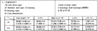
My (Glenn's) values, the 447 cam used in the XX650F2 are shown attached.

The values I determined are as follows:

So for the intake
36 + 180 + 68 = 284°
(284 / 2) – 36 = 106° = lobe center
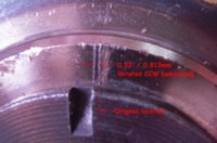
This 106° is what I needed to get to which was 3.5° of CCW rotation on the cam.

The second picture is the angle change I needed for my cam. The last shows my degree wheel and dial indicator setup.
 

Attachments

  • 447 cam specs.jpg
    447 cam specs.jpg
    45.9 KB · Views: 142
  • Re-index of my Cam.jpg
    Re-index of my Cam.jpg
    169.7 KB · Views: 163
  • DSCN1963.jpg
    DSCN1963.jpg
    230.8 KB · Views: 147
Last edited:
Back
Top