Clutch drag elimination, a different approach

MacMcMacmac

Failed Hedonist.
Top Contributor
Messages
596
Reaction score
1,061
Points
143
Location
Ottawa,Canada
Hi guys. Driving around on my XS this past week has been bliss with the unseasonably hot weather here in Ottawa. The only drawback was the persistent clutch drag that makes finding neutral so difficult at a stop. Yes, I have absolutely all slack taken out, and the pin screwed into to lightly bottom against the steel ball.

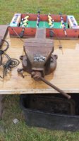
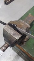
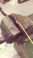
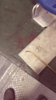
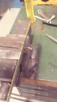
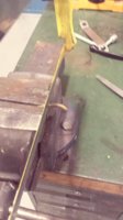
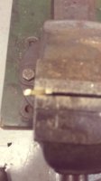
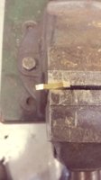
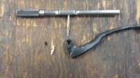
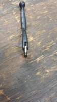
I have been thinking a lot about this, and I see much experimentation has taken place to find a remedy. i thought about how I could mod the spiral mechanism to make it a two stage system, how to make the spiral steeper, how to increase the cable pull, but nothing really jumped out at me. The spiral mechanism is pretty much as it is going to stay. Then I thought, maybe we could tackle this problem from the other end. I have a spare clutch lever here from my old 650 Seca, and I was looking at how it could be modified to increase the cable pull. I looked at how the cable recedes into the clutch lever as it travels through its arc of operation. There is a deep slot in the lever which allows the lever to travel around its pivot point without interfering with the straight pull of the cable. Then I had a thought, what if we intentionally did interfere with the straight path of the cable. What if, as it sank down into the slot, it found a solid object that prevented it from going further down into the slot This would have the effect of increasing the the distance the cable would have to move, by providing a fulcrum in the lever that the cable was forced to pivot around. I thought that extra travel just might be enough to gain us the extra few tens of thou to get the clutch to disengage cleanly. The pivot could be a roll pin with a bit of stainless tubing around it to allow it to rotate to minimize wear on the cable. Maybe a sold cam shape could be made up and forced into the slot? who knows. Maybe something to while away the oncoming winter months. I'll see if the Seca lever might be the same part as my XS and try something out.
 
Last edited:
Hey, Mac. Similar thoughts here.

I like the "arched cam fitted into the slot" idea. Forces the cable to travel a bit longer distance. Like my "soft throttle" mod.
SoftThrottle.jpg


But, want to avoid small radius arcs, that could stress the cable and lead to broken filaments.
ClCbl-B03c.jpg
 
Last edited:
I've been thinking about removing some of the material in this area to allow the clutch lever to open up just a bit more which will give you a bit more overall travel. Of course it will make the reach a bit longer for those of us with shorter fingers...(keep the jokes to yourself)

This is just a random pic I found on the net, not something from a 650.
DSC1467adjustment.jpg
 
Whilst I understand what you are trying to achieve your enemy will be the diameter of the pulley you create to run the cable over.
If the diameter is too small then the cable will break as illustrated in Mr TMXS!b's photo.

Whilst I can't find anything to support it I seem to recall that a ratio of 40:1 (pulley diameter: wire diameter) is the sort of ratio you would aim for.

If we take our throttle as an example that gives some idea of the diameter you would need. That said it would need to be larger due to the thicker cable.
 
why not shorten the radius of the pivot pin location on the worm actuating arm ?
I can't remember the maths involved now and too lazy to refer to my books but 2m or someone is sure to work it out .Something about moments of arc and half a chord ....

Basically if you shorten the worm arm you increase the arc that the worm arm travels thus increasing clutch plate seperation.
I think Mikesxs used to offer a modified worm arm but its a simple job to just drill a hole in the arm as I did .
Be interesting to work out how much clutch lever movement or plate seperation is achieved with what reduction in worm arm radius
xs650 clutch worm final position.JPG

XS650 Clutch Worm Mechanism parts2.jpg
 
I did this mod as well I believe, and I have no trouble finding neutral usually...there are days though.... I think my foot is heavy handed some times ! LOL
.....
Bob.......
 
You can replace a ball with a 5/16" dia. rod of whatever length you choose, to get more plate separation. What can you really do other than try and get more separation?
 
Yes, moving the cable attachment point closer to the worm will increase the pressure plate movement. When the worm on my 75 cracked I bought Mike's new unit. I tried it in both holes. Out further the lever pulled easier but won't open the clutch as much. In closer, pulls a bit harder and opens the clutch further.
I use the closer hole. The bit stiffer lever is a good trade off for the better clutch action.
Leo
 
20170919_160958.jpg

Cleaned up the throat figuring I could solder it in. No dice.
20170919_162340.jpg


Fits well.

20170919_171603.jpg

Won't win any workmanship awards...

20170919_173430.jpg

Drill and tap for 8-36 X 5/16 set screw. thin end to the cable end, thick end to the open end of the slot. I gave it a gentle ramp, and a curved let down to ease the burden on the cable.

20170919_173807.jpg

Looks factory-ish....not. I should have drilled a bit farther out towards the edge. As it was, I barely caught the bottom of the cam, but it works becaue all it has to do is keep it from moving. The cable load will press it into the handle, and the cable end secures it from sliding backwards.

Annnnnnnd.........no improvement. I think it needs a more radical upsweep at the end, not a downward curve. Or a steeper ramp. At any rate, the cable will begin to foul the adjuster bolt and lock nut if the lift is too great. You would have to orient them so the cable passes through the slot in both if you're going for a radical lift. Probably doable. I may investigate further if the warm weather holds.

I have had a different, and far more radical idea. Let me start another post..
 

Attachments

  • 20170903_150414.jpg
    20170903_150414.jpg
    175.8 KB · Views: 158
  • 20170919_160907.jpg
    20170919_160907.jpg
    87.9 KB · Views: 174
  • 20170919_161128.jpg
    20170919_161128.jpg
    92 KB · Views: 125
  • 20170919_161134.jpg
    20170919_161134.jpg
    94.3 KB · Views: 128
  • 20170919_161226.jpg
    20170919_161226.jpg
    92 KB · Views: 163
  • 20170919_161233.jpg
    20170919_161233.jpg
    102.4 KB · Views: 141
  • 20170919_161315.jpg
    20170919_161315.jpg
    75.4 KB · Views: 184
  • 20170919_161437.jpg
    20170919_161437.jpg
    77.7 KB · Views: 140
  • 20170919_161442.jpg
    20170919_161442.jpg
    109.2 KB · Views: 147
  • 20170919_173435.jpg
    20170919_173435.jpg
    103.8 KB · Views: 158
  • 20170919_173757.jpg
    20170919_173757.jpg
    126.1 KB · Views: 153
I'll steal Peanuts post to illustrate my idea:

why not shorten the radius of the pivot pin location on the worm actuating arm ?
I can't remember the maths involved now and too lazy to refer to my books but 2m or someone is sure to work it out .Something about moments of arc and half a chord ....

Basically if you shorten the worm arm you increase the arc that the worm arm travels thus increasing clutch plate seperation.
I think Mikesxs used to offer a modified worm arm but its a simple job to just drill a hole in the arm as I did .
Be interesting to work out how much clutch lever movement or plate seperation is achieved with what reduction in worm arm radius View attachment 106267
View attachment 106268

Imagine a very thick washer that it attached to the top of the steel disk that the arm is welded to.
The washer is below the arm, which has been removed and welded back on.
Think lever arm-----> washer----->disk.
This washer will act as a cam, since it will have two protrusions on the bottom that will lie just counterclockwise of the two screw heads holding the spiral gear in place on the case.

As the disk rotates, the washer's protrusions will reach the phillips head screws and begin to climb up onto them. The protrusions will cam the entire spiral gear outward from the case, giving a whole heck of a lot more movement than the stock setup. I am thinking the protrusions may be heavy rivets peened into place on the washer. Alternately, the three small bosses visible on the cover could be drilled, and three rivets put in those to act as the load bearing points. This would be trickier, since they don't seem to be equidistant from the center of the spiral.

The spiral mount would be made movable by slightly enlarging the holes in the flange.

The screw heads would not be torqued down onto the base, Instead they would sit up from them, and there would be a pair of heavy springs to press the spiral gear flange in place. This would necessitate modifying the case somewhat, perhaps lowering the area where the two screws go. I am thinking it might be easier to drill completely through the case and use longer screws to get enough depth for decently strong springs. The spiral gear would be prevented from rotating by the two screws. They could have some of the thread removed to provide a smooth shaft for the spiral flange to slide up on.

Maybe it would be easier to mount a long, heavier, wider spring from the inner case to push out against the disk that way.

I guess it's difficult to visualize from the description.
 
strewth you sure got a vivid imagination Mac :D i had to read that 3x times to get my head around it lol.

You should only be looking to achieve an increased clutch plate separation of 2-3mm maximum or I would expect either the top clutch drive plate will lose engagement on the spline or the springs would bind .

Why not try the worm arm pivot relocation first and see if that does the trick it could save you an awful lot of unnecessary work.;)

When I drilled a new pivot pin hole in my worm arm it had the added benefit of saving an extra mm of cable travel simply by eliminating the wear between the old pivot pin and pivot pin hole which was very sloppy.
 
Yeah, that is getting a bit too involved. Hole it is!!

Sometimes its nice to have a challenge and to try something a little different and I'm the same in that respect but I have to say there is so much continuous maintenance, servicing and repair to do on these old bikes as it is I'd recommend taking the easy option first .

if you ever remove the clutch assembly there are a lot of things you can do to improve clutch plate separation and there are numerous threads on here about that.
 
Dang, my lever arm already has the hole near the pivot. I tried putting one closer, but it just fouled the bend when it tried to move. Have to keep thinking on this one. I have everything snugged to the max, so much so that even twisting the adjustment bolt in the handle mount 2 turns cause massive clutch slippage, so there is no adjustment left to work with. Might be hydraulic clutch time.
 
Mac ...don't go do anything that drastic yet .

The stock clutch can work very well once it is sorted properly.
If you have the cover off already I think the time has come to strip your clutch and give everything a good clean.
Check the thickness of your plates are within spec and frankly if you go that far you might as well replace them and your needle bearing pack too for the minimal cost.
Also replace your clutch push rod bush and oil seal at the same time if they are worn or leaking

Its really important to dress the edges of the clutch basket 'fingers' (can't think of the right term at the moment), so that the clutch plate tangs do not drag on the indentations .Filing these indentations and also all the tanks of the plates makes a significant improvement in clutch operation.
I rebuilt my clutch a couple of years ago and its a dream to use . Perfect separation , no drag whatsoever and easy smooth lever pull.
 
Personally, I'm not 100% for the extra hole modification in the worm arm.... as it makes the clutch lever MUCH harder to Pull.
i lean toward adding length to the clutch worm arm rather than reducing it...an easy clutch pull is a very important thing and you hardly ever see it. but with 2M's indicator experiments it's clear that the clutch pushrod is being pushed far enough...( I thought that was the whole problem...but it's not! ) .....
so I'm thinking now of adding 1/2" of steel to the worm arm and trying to get a bit more cable pull in order to make the clutch allot easier to pull....
I've had several easy "clutch pull" Bikes and a few that were very hard and almost unusably hard. with the extra hole in the worm lever arm and the clevis moved to it the XS650 moves up in the list of hard clutch pull bikes .....for me anyway. !.
if the clutch is easy to pull in there is no problem leaving the bike in first for the 2 minute wait for the signal change to occur.
if however its a really hard clutch Pull, you'll be looking to find neutral before the light changes just so you don't have to hold that pressure in your left hand !..... and on a easy clutch pull you can feather the clutch much easier and more accurately on a hard clutch pull machine it's usually just change the gears and dump the clutch and feather the throttle instead..... more than once that has caused problems on freshly graveled roads.... and I prefer to use the clutch not the throttle when ever possible.
this is a "to each their own " thing but an easy to pull clutch is something you learn to love , it doesn't seam that important at first but it really is very important.
......
I remember first getting on here I thought oh KOOL there is clutch Mods for making the clutch easier to pull as stock is a bit stiff....
but found out the mods only made the clutch harder to pull in the end....
do any of you have any ideas on how to make the clutch easier to pull ?
I'm thinking of adding 3/8" to 1/2" to the worm arm but given the limited travel of the clutch Pushrod I think that would be leaving the clutch in the "Hard to find neutral" range...... and I don't want that either.....
any Ideas ?
.....
Bob......
 
Personally, I'm not 100% for the extra hole modification in the worm arm.... as it makes the clutch lever MUCH harder to Pull.
i lean toward adding length to the clutch worm arm rather than reducing it...an easy clutch pull is a very important thing and you hardly ever see it. but with 2M's indicator experiments it's clear that the clutch pushrod is being pushed far enough...( I thought that was the whole problem...but it's not! ) .....
so I'm thinking now of adding 1/2" of steel to the worm arm and trying to get a bit more cable pull in order to make the clutch allot easier to pull....

given the limited travel of the clutch Pushrod I think that would be leaving the clutch in the "Hard to find neutral" range...... and I don't want that either.....
any Ideas ?
.....
Bob......
Bob if you have a hard -to-pull clutch lever then there is definitely something not right about your setup and/or components.

Extending the worm arm is not the way to go you'll end up with too little travel to seperate the plates adequately.

I would suggest you first go right through your clutch components and check to see if you can identify where your friction drag or binding etc is occurring.
My clutch was rebuilt after 18000 miles and it is so easy to pull a child could operate the clutch
 
Back
Top