Tuning.....Where the hek to start!

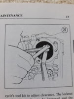
+1 - and please note that those are not simply normal 6 mm screws.

The bottom end which bears on the top of the valve stem is hardened and has a special profile which is required for the valve to operate correctly.

When I got my 1976 C model, one of those square ends was busted right off - don't know where it went...:yikes: - so I replaced all four of the adjuster screws with Allen head adjuster screws from MikesXS - and haven't had any difficulty since.

Many people use a valve adjuster screw from VW air-cooled engines or a certain model of Porsche engine which fits perfectly - and apparently, they work very well too (although there are reports of counterfeit parts around).

p
 
Your rough running and occasional backfires could very well indicate the timing was off a little. It was close enough for the bike to start but probably not exactly right. You're in for a treat when you go to set the points and timing. If you enjoy Chinese water torture, you'll love this procedure, lol. You're actually setting 2 separate little ignition systems. Points gap and timing must be set individually on each one then for best running, they should match set to set. You'll need a timing light to accurately check and set the timing.

For the valve adjusting screws, I use a 4mm open end from a metric ignition wrench set.
 
Re: points plates. If the JIS holes are stripped/rounded you have a second chance as the screw also take a straight blade. But it needs to be a flat ground driver, not a "V" type grind. Tapping with a hammer will help loosen the screws.

Paul Sutton's tip about making a wrench is good. Yamaha supplied a specific wrench in the tool kits if you can find one. A 4 mm spanner will also work well.
Or if you notice when tightening after contact the lock nut will turn the shaft about an 1/8th of a turn when tightening. So I have run the aduster down finger tight back the adjuster off an 1/8. Run the lock nut down to contact then tighten to calibrated finger torque and end up with a respectable meatball mechanic gap.
I do not encourage anyone else do this but in real life hickabilly terms it has worked for me. If RG were still around the argument would commence. I'm pretty sure 5twins, 2M, gggGary and Grizld1 would also look sideways at this procedure.
 
WER, +1 on sometimes just getting it done. A little practice finger setting, a few tries, goes a long way on that valve adj screw. Get to know it !
And 5 twins is right about the points setting "chinese torture" too till you practice. But hey, its actually kinda fun if you don't hurry. These pics help make sense of it , or did to me.
 

Attachments

  • 20171210_091419.jpg
    20171210_091419.jpg
    114.9 KB · Views: 171
  • 20171210_091419.jpg
    20171210_091419.jpg
    114.9 KB · Views: 164
Whatever works for you on the valves I guess. My "special tool" for valve adjusting is a big rubber mallet. Often, once I tighten the lock nut while holding the screw from turning, my setting becomes a little looser. I think that's because of the play in the adjuster screw threads. Tightening the lock nut pulls the screw up slightly, increasing my play setting a hair. When that happens, I grab the rubber mallet. I'm aware that tightening the lock nut without holding the adjuster screw usually tightens it too. So, I place a box end wrench on the nut and give the other end a couple whacks with the mallet, without holding the adjuster screw. This usually tightens the lock nut a little more, and the adjusting screw along with it.
 
Here is a great recommended technique, but it almost takes 3 hands ?
The feeler gauge is just hanging there, no hands required, especially if it's just a single blade removed from the set. I took .003 and .006 out and keep them with my 10, 12, and 17mm wrenches and jis bits ;)
 
Whatever tweaking technique you use, patience is your friend; check and correct instead of trying to put clearance "right on the cat's ass" in one go. One thing to consider is that valve stems cup with wear, and a feeler gauge will read the edge of the cup, not the true contact point. If you take a reading with a feeler gauge then set up a dial indicator on the rocker arm and read the movement, you can derive a correction factor. For example, if you find out that the rocker moves .007" and the feeler gauge tells you the clearance is .006", set the valve with a feeler gauge that's .001" tighter than the desired clearance. You don't need to jump through this hoop with every adjustment; it's enough to record the correction factor for each valve and verify it every 5K miles or so.
 
Along the lines of Grizld1, I always find that once the lock nut is tightened the exhaust gap of 0.15mm (0.006 inch) increases slightly to just less than 0.18mm. So when setting the exhaust at 0.15mm I use the 0.13mm feeler and then my result is very close. Not an issue if the gap is a bit bigger, I just like to get as close as I can to the factory recommendation - but definitely not less than.

.......I do find 3 hands would be very helpful often.
 
With the Ramair air Filter, on the BS38 Carbs which have a 54mm neck are people going with the smaller Ramair 52mm or the 55mm and clamping it down? Was going to buy the oval shape, I'g guessing there is no problem with that? Also, what is the correct lubricant for the felt pads found at the points?
 
Last edited:
I use a 2" UNI filter on my BS38s, which is about 51mm. They fit perfectly. I'd say go with the 52mm Ramair.

Yamaha recommended a couple drops of motor oil for the felt pads but I use an actual points cam grease. Not easy to find these days but I'm sure with all the old Brit bikes running around your country, something is available.
 
On another note I found this video on youtube BUT surely this is not correct, this is not actually adjusting anything??

I guess what hés explaining is a procedure to find your TDC but hés not explaining the adjustment to be made. You find the point where the clearance is the biggest then you adjust to the required value. This is unclear in the video but sort of covered in the comments underneath. Am I right?
 
Also, my feeler gauges go up in 0.05 increments. The valve clearance for the internal is 0.06 mm, can I use my 0.05 without issue? The set I bought is however a very good (not cheap) accurate set.
 
.05mm (.002") is too tight in my opinion. Most of us use .003" for the intakes, or even slightly larger.
 
Thanks 5T.....that's .0762 mm, I'll try to find a finer set. Would .01mm (.004") be ok?
 
Yes, .004" would be fine. In fact, that was the intake spec for the '78 model. Mine ticked rather loudly using that so I closed it up to .003". That setting quieted things right down. It's pretty much become accepted practice to use .003" on the intakes and .006" on the exhausts for all models. Yamaha changed the specs several times during the production run and there really was no apparent reason for it. There were no radical changes made to the motor that would warrant them. Intakes varied between .002" and .004", exhausts between .004" and .006".

And speaking of feeler gauges, my all time favorite is the Cal-Van #229 .....

fplTKji.jpg


This was probably the first feeler gauge I ever bought many, many years ago. Recently, I thought I'd get a replacement but discovered they no longer make it. I was able to find a couple N.O.S. ones on eBay though. What makes this gauge so nice, besides it's "Made in USA" quality, is that it contains just the sizes you need and use most. Also, sizes .002" through .008" go in .001" increments. This allows you to use the "go, no go" method when checking your valves.

rGyB1oI.jpg
 
Paul - are you running an electronic ignition?

There are two for the XS650 - the Boyer-Bransden (B-B) and the PAMCO. Both are well regarded and have their advocates. The PAMCO seems to be more common in North America and I think the B-B is made in the UK. These units are basically set and forget and a key advantage is that they can drive a higher voltage ignition coil and IMO, remove at least one variable on the tuning front.

Earlier units required you to retain the stock ignition advance mechanism (which lives inside the RH end of the cam housing under the circular chrome cover) but PAMCO Pete just released a brand new unit (less than $200 USD) with a built-in timing advance capability that looks very slick. There was an intermediate “Mk-II” version of the PAMCO that had an electronic e-advancer which eliminated the mechanical timing advance unit and used electronics in a separate little box but it required you to run more wiring and find a secure place to mount the box. The latest unit (just released last week) eliminates the separate box and looks really easy to install.

Anyhow - onward & upward!!

Pete
Sorry Pete, late reply, not using electronic just points!
 
Ok- well, they work just fine and once you get the hang of setting them, it’s not a big deal.

As with everything - stare at the manual and stare at the bike and work methodically.

Cheers,

Pete
 
Back
Top