On your stock system there was a few things that may not function with your new switch. Self canceler, is one. The RLU is another.
your diagram has some numbers, these are in a plug correct? There are others listed just by color, I assume these are out by themselves.
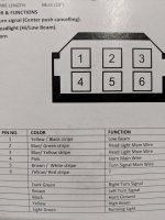
New switch plug your harness.
#1 yellow-----------------------------------Dark green both go to the headlight low beam
#2 blue green-----------------------------
#3 blue/yellow----------------------------
#4 pink-------------------------------------Pink wire from horn
#5 Brown/white--------------------------Brown /white from flasher
#6 Yellow/red----------------------------
D/Gr----------------------------------------D/Gr right turn signal
Brown--------------------------------------Chocolate or dark brown Left turns signal
Black---------------------------------------Hook to ground on frame or into the black harness ground
Yellow-------------------------------------Yellow headlight high beam.
L/gr-----------------------------------------
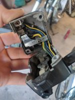
On your stock system the other wires from your harness hooked the left side switches to the Reserve Lighting Unit and the turn signal self canceler. The #6 y/r may hook to the R/Y on your harness. This goes to the self canceler.
On the headlight dimmer switch of the new switch the blue/green or the blue/yellow is power in. One of these wires should hook to the yellow/blue from the RLU.
That's about all I've got.
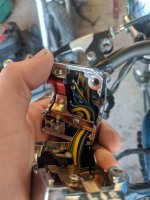
Do you still have the stock left side switches? If so you can use you meter to check both the old and new to compare what the switches send power to which wires. This may help get everything working.
I don't know just what you are doing. Trying to keep it stock or to simplify things.
As far as simple goes this diagram work well. It shows a basic points ignition with the separate regulator and rectifier. In boxes it has the later TCI and combo reg/rec. E-start is in the upper right corner.
It doesn't show the turns, but are not hard to add in. You can hook to the Brake light fuse, run a brown wire to a flasher, From the flasher with a brown/white to the new switches brown/white wire. From the new switches out to each side, right is dark green, left is dark brown.
Leo