WJL AKA Wrenchjohns Legacy 70 XS1 in gggGary's hands

And goober on the counter shaft seal.
20191021_113746-1.jpg


I'll just throw in here about how that seal works. You can see where the lip rests on that collar. The "common leak" is when the sprocket is loose. The other "seal" is the back side of that collar against the bearing. None of the accessible surfaces are seals so no adhesives, sealers should be used out here.

Hey bob how deep is the outer part of that seal?
 
Not sure if appropriate for aluminum but have seen the "Lock-N-Stitch" technique used to repair cracks in cast iron engine blocks and heads. "Screws" pull cracked pieces together when installed correctly. Seems counter-intuitive but has to do with shape of "screw" threads. Company is located in Turlock, CA. Might be worth a look?....... Best wishes with the repair................Wesley
 
That worm gear is a head scratcher. Why would someone do that, cut the tin seal shroud off?
 
Worrywart checkin' in here.
Something to consider, load distribution on the left engine cover.

The force exerted on the clutch pushrod can get up to 400 lbs.
That force is countered by 4 cover screws.
Greatest load on screw #1, followed by #2, #3, and #4 (least).

ClutchCoverLoads.jpg


Which means that screw #1 will be experiencing at least 100 lbs tension, pulling on the crack.

Recommend closely watching the crack while pulling the clutch, see if you can observe any separating...
 
Gary , something I have noticed with my carburetors, is that I’m having some difficulty in keeping the throttle action synchronized. Being non linked the two throttle cables have to be adjusted for length independently of each other to assure that the butterflies are turning at exactly the same time.
With my bike, I’ll get them just perfect, ride my bike several times and I notice the engine will start this shaking when you first twist the throttle. ( due to only one carburetor starting to open ) It took me a while to figure out, that my synchronization gets out of whack for some reason and I have to re adjust the cable length/ free play.
I wonder if you or anyone else with the early carbs run into this.

Hey, Bob. Yup, been there. On mine, found that most of that has to do with how the throttle cables are routed, how they react to handlebar rotation, and how they settle into the emergence zone between the bottom of the tank and frame.

During handlebar turning, the cables bend, and if one bends more than the other, the length changes. Same with where they come out from below the tank. Riding and vibrations will have them settle to a position that may be slightly different from where they set right after installing the tank. The protector springs (between cable and tank) will also settle.

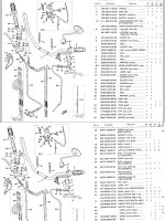
Use part #31, cable clip, to keep the cables together. The parts list shows 2, but doesn't show where precisely to put them.
70-73-HandlebarCables.jpg

I have only 1, positioned about 6" from the adjusters. The way my cables are routed, on the rightside of the frame, keeps them together for the rest of the way, until they separate behind the coils. You can kinda see pics of them in my clutch cable thread.

Post #8.
http://www.xs650.com/threads/xs650-clutch-cable-experiments-and-tidbits.32945/#post-334333

With them clipped together, routed together, kept close to the frame, and protector springs slid fully down, they don't fall out of sync...
 
tscrew #1 will be experiencing at least 100 lbs tension,....
watch the crack while pulling the clutch,... observe any separating...
throttle cables....clipped together, routed together, kept close to the frame, and protector springs slid fully down, they don't fall out of sync...

2M will check both those items, thnx! I placed a shim on ONE throttle shaft other side wouldn't take one without binding. Noted a difference in distance from idle stop arm to adjustment screw boss with screw retracted, between the carbs, an area of concern.
From an earlier conversation with you I decided to remove and check the "rubber" manifold crossover tube. Loosened the clamps and as you suggested might be the case, it was so brittle it shattered on attempted removal. Seriously considering adding an isolation valve and or vacuum taps instead of just a replacement so carbs can be accurately synched and then decide if it runs better with or without the cross connection.
 
Brittle crossover tube? Glad you checked it.

That crossover tube may have been part of an effort to subdue the unstable idle. Since later models don't use one, we could probably declare it as unnecessary. I've found irregular, non-round throttle bores in all 4 of my '71 carb bodies, and have strong suspicions that is the actual source of the unstable idle problems. As long as the throttle plates are light checked, and well centered, the idle should be fine.

The shim on the throttle shaft is indeed concerning. Hopefully it's just a manufacturing fluke, wrong length shaft or mis-machined throttle shaft bore.

Sure would be nice to find some more of those cable clips...
 
Worrywart checkin' in here.
Something to consider, load distribution on the left engine cover.

The force exerted on the clutch pushrod can get up to 400 lbs.
That force is countered by 4 cover screws.
Greatest load on screw #1, followed by #2, #3, and #4 (least).

View attachment 152459

Which means that screw #1 will be experiencing at least 100 lbs tension, pulling on the crack.

Recommend closely watching the crack while pulling the clutch, see if you can observe any separating...

I don't think he will have a problem with flexing. The spare engine in my 72 threw it's chain at sometime in it's life. The part of the case bolt 1 is in is completely severed. I see no movement in the broken piece or side cover when pulling in the clutch. I've put over 3000 miles on it this year. My guess is bolts 2,3 and 4 can handle 133 lbs apiece.
upload_2019-10-22_8-20-27.png
 
I have a couple of sets of BS34's that are "start up ready" if this continues to fight me, I swear.... LOL

I am really not a purist in such matters, as evidenced by all the electronic replacements in my ignition and charging. If you’re not showing the bike, just make it a nice reliable rider!
 
Hey mailman plugging away on my phone down in the shop I left out that it's BUMPER epoxy.
View attachment 152434
And thanks for the seal measurement, you are a gem, think that gives me plenty of meat left to retain that seal.
I'll be interested in the longevity of your case crack repair with the bumper epoxy, which I've never used.
I had the very same case crack in one of my engines; used JB Weld successfully.
 
Hang on to that black nylon female worm part you removed. I think they may actually be a little better as far as wear goes. The black nylon insert is harder than the earlier white ones. Doesn't look like you'll have any tin shroud clearance issues (I'm still scratching my head, lol). The only clearance issue I ever encountered was with the cover gasket, and that is easily remedied by trimming some off in that spot.

rU31D5g.jpg
 
Back
Top