Been thinking along those lines myself 5T. Perhaps buoyed by the modest successes I experienced with the headlight wiring, following your advice, I held off committing to purchase the ready made components and considered the VR 115 alternative. As usual, guidance on the Forum is strong and the savings are considerable, (over $200). Auto-electrics are still Terra Incognito to me, the function, (or even the appearance), of a diode remains a mystery and the texts on the purpose of 3 phase equipment soon have me nodding but I have decided to experiment with the VR115 set up first. If I screw up, it'll only add $60 to my bill and I might learn something.
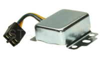
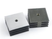
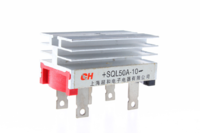
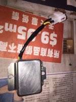
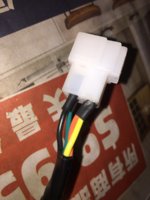
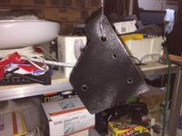
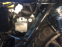
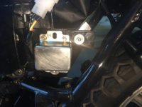
To this end, I have ordered a VR 115 regulator on eBay ($46 AUD delivered here). I considered the 35A rectifier shown in pic 2, (RG says that we only really need 25A but he put a 35A on his) and separate heat sink plates, (pic 3). Those totalled out at around $15.00 for several examples of each. I then caught up with this combined rectifier and sink, a 50A 1000V 3 Phase heat sink base metal case Bridge rectifier, (pic 4) for the princely sum of $4.22, (pic3). The thing comes with a predrilled central mounting hole and seemed too good to pass up. Two drawbacks that I can see are that some of these models have the annotation that they are suited to brushless generators although the ones I purchased gave this description;
High quality bridge rectifiers used for conversion of an alternating current
input into a direct current output.
The top and internal part are well welded which ensures a more stable
performance.
Base is small and has a large over-current capacity, good heat dissipation and
low voltage drop.
These high power, high frequency bridge rectifiers are used for power supply.
No. of Phases: Three;Model: SQL20A
Material : Resin, Metal
DC Output Current: 20A
Repetitive Peak Reverse Voltage: 1000V
I don't understand the "brushless generator" bit but I just fitted new brushes to mine so I know she has them. The other thing is that they won't be delivered 'til the end of March. Working at that rate, if hostility did break out between the People's Republic and Oz, I would have died of old age before their forces arrived here! Oh well, I've still got the carbies to play with.
Let me know if you think all this stuff is OK - I've certainly got time to change my mind. So..... $46.01for the reg. + $8.43 for two of the recs and at least three bottles of Jack Daniels with what's left over to celebrate my pecuniary economy.
Cheers