Several XS650 (G?) wiring questions - no headlight, no indicators and more!

The oil sight glass on your right engine side cover could indicate you have an '81H model. That model would have a green plug in the headlight bucket with a black and black/yellow wire coming from a clutch safety switch on the clutch lever. It wouldn't be for your front brake light switch. The '81 wiring diagram indicates that would use brown and green/yellow wires.

Much appreciated - I had no idea there was a clutch safety switch on these bikes - the clymer manual doesn't seem to refer to one on any of the wiring diagrams - and there are 10 diagrams in total!
 
That "lonely" yellow wire by the stator plugs is the other end of the yellow wire in the connctor at the safety relay. There should be a cloth covered yellow wire coming out of the loom from the stator for it to plug into .....

LrbvgGA.jpg
That's really helpful and much appreciated - there is no sign of any yellow cable coming from that loom - totally absent.
I am now wondering if it is a none standard stator or why the yellow wire would have been removed for any logical reason...?
 
I find those things really difficult to read - particularly for example. when you have multiple black wires going into the headlamp bowl and then which one goes to which
All the black wires are ground. Just use whichever has the right length or right connector.

The first time I opened the headlight i was making copious notes...until I realized there's only one connector of each type, so they can only go back one way :)
 
I have another, very basic question...
could anyone confirm, that the colour of my turn signal wiring is normal.
I ask, because I keep seeing references to "chocolate" and "dark green" and in one case, Team Junk wrote that it was easy to mistake the "chocolate" wire for black!
Well, that's not true for my machine - not by a long way and yet, I am pretty sure this is an OEM loom (if only because all wires in the connector blocks colour match).
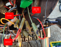
Anyway, my "dark green" is 100% not any kind of dark green I've seen before - it's sort of pale mint green and what I think is the "chocolate" wire, could never be confused with "black"
The pale green and "chocolate" (light brown) are common to the front and rear bundle (see pics) - so I assumed that this pale green and mid brown MUST be my turn signal wires.

But I DO have a dark brown (almost black) wire but only in the front.
I DO have a dark green wire, but again, only in the front
I also have another mid green wire, going to the headlight bulb.

With the pale green and "chocolate" wires hooked up to my indicators, with ignition key to "on" I get a solid lit (not flashing) right front turn light. Nothing from the other three and the turn switch doesn't do a thing.
I have 12v to the brown and brown/white wires to the indicator relay
I have 12v to both sides of the turn signal switch.

I am maddeningly confused right now!

See (even more) images of front and rear wiring
rear.png

new.png
 

Attachments

  • front.png
    front.png
    2.2 MB · Views: 230
  • upload_2020-4-20_13-51-49.png
    upload_2020-4-20_13-51-49.png
    5.6 KB · Views: 202
Yes, it seems the turn signal wire colors don't always match up exactly as far as their shades of color go. Maybe they fade over time or maybe Yamaha just didn't strictly adhere to their own color rules, lol. The green and brown at the rear of the bike are definitely the turn signal wires, even if the colors are off some. There's nothing else back there they could be for. They run up into the headlight bucket and plug into the double brown and green. I think if you test each one for continuity, you'll find those single male bullet dark green and chocolate wires in the bucket are the other ends. The clipped black wires you found coming out of the double green and brown in the headlight bucket are probably remnants from the original front signals. They had black power wires that plugged into those doubles along with those two wires from the rear of the bike.

So, remove those clipped black wires from the doubles. The dark green double (or in your case, lighter green) is for the right signals. Connect that single dark green and your front right signal to it. The "chocolate" double is for the left signals. Connect that single chocolate and your left front signal to it.
 
I'm not sure if this helps but in the headlight bucket there are two green wires, one dark green that goes to the turn signal and one green wire that goes to the headlight. It's not hard to get them mixed up.
The flasher unit is designed for the load of two 27 watt turns signals and a 3 watt indicator light. It will only flash when it has that load. So when you turn the right turn on and only the front lights and no flash means the rear turn is not hooked up or the bulb is blown. Possibly a bad ground.
Usually they won't flash unless the engine is running.
The stock turns signals have a single element bulb. It has one wire coming out the center of the mount bolt. Thuis is the power wire. The bulb grounds through the body. A black wire with a loop get hooked on the mount bolt under the nut. Thus black wire plugs into the black harness ground.
For testing you can make a jumper wire to plug into the socket the flasher, put the jumper from the brown wire to the brown/white wire. This allows you to eliminate the flasher as an issue on lighting the bulbs.
On the brake switches, both front and rear a brown wire feeds power to the switches. A G/Y wire sends this power to the brake light.
Leo.
 
Another thing on the turns, Some have found when you open up the left side switch hosing the rurns wires have poor connection of the wires to the switch. You may have to resold the wires.
On the headlight as others have said in the stock system a yellow wire come up from the stator to power the safety/ lighting relays. If yours does not have a yellow wire coming up from the stator it could be your bike has a PMA conversion on the alternator.
A PMA does not have a yellow wire to power the relays.
Does your bike have the stock field excited alternator or has it been converted?
Leo
 
I was studying your pics. In your pic that shows the lonely yellow wire, your 6 wire plug doesn't have the right number of wires. your has the three whites, a green and a light blue. If you look at 5twins pic in post #17 you will see there is three whites, a green a brown and the light blue. Your missing the brown wire.
On the stock charging system a brown wire feeds p[power to one brush on the stator. The brown also feeds power to the reg/rect. The reg half of the reg/rec reads the voltage on the brown wire. If this voltage is low it grounds the green wire on the other brush on the stator. This causes the stator to put out AC voltage.
This AC voltage is sent out on the three white wires to the rec half of the rec/rec and gets converted to DC to charge the battery.
Perhaps your brown wire comes up from the stator somewhere else to get hooked up to the brown wire. Your yellow wire may be going there too.
On the wire bundle coming up from the stator, This wire bundle comes up just to the left of the frame by the drive chain.
It look like your PO cut the black cover off your harness at this point. Somewhere along the path this wire bundle takes you may find your yellow wire and your brown wire.
In your second pic in post 25. The dark brown and green wires you have going to nothing are your turn wires. The mint green that runs from the rear turns up to the headlight bucket has a two plug sock. Plug the dark green wire into that socket. Plug the right front turn signal in the other side of the two plug socket.
On the Chocolate side, or dark brown there should be a brown that comes up from the rear with a two plug socket like the green had. Plug the chocolate wire I one side of this two plug socket. Plug the wire from the left front into the other side.
This should get the lights wired right at this point. As mentioned your turn switch may need some attention.
I see your turns are LED's. If they have two wires coming out of them there may be two ways to wire them. One wire may be power, the other ground. Or one wire is power for the turns and the other is power for running lights, ground through the body.
You may have to do some testing to be sure.
With a jumper wire from the battery negative to the mount bolt of the signal and another from battery positive touch the positive to each of the wires from the signal while watch the signal to see it light. If one wire lights it up bright and the other dim it is set up to run as running and turns. If not try hooking the battery neg to one wire and pos to the other. If it don't light try reversing the wires. Most LED's are polarity sensitive.
Once to find how it lights you cab then know how to wire it.
Leo
 
Last edited:
Hi all,

Thanks in advance for any pointers.
I am in the UK and have a US import XS650 with plastic side panels, single tap tank and take off seat - G model? Special / Special II?
I am using a stock loom, that is in OK condition, but many of the connector blocks are brittle and broken - I presume from sun baking, but otherwise, decent.

I am using Clymer manual with its black and white coded wiring diagram.
I have several electrical problems

  1. Indicators/Turn signals
    Clymer says my indicator cable should be Dark Green - it's totally a light green, almost mint colour at top and tail of the bike
    My right hand turn (not) dark green wire terminates in a double female bullet connector - why would the turn signal need to flow onto somewhere else other than the bulb and which wire is supposed to connect to the other female socket here?
    With the ignition on, and all indicators wired correctly (as far as I can see!) I get only one front indicator lit and it does not flash - there is no sound from the indicator relay under the tank and I've swapped the relay already to no effect.
    Also, the indicator switch on the left handle bar control does nothing - the front right hand turn lights up, solid and only turns off with the ignition switch !

  2. Headlight does not come on after ignition - strange yellow wire near alternator wiring block
    There is an unconnected yellow wire with a male bullet connection, coming out of the loom, next to the bundle that connects via a block to the alternator wires.
    I can see no female bullet yellow wire anywhere in the vicinity to connect this yellow wire to.
    If I jump this yellow wire to the 12v positive battery - the headlamp comes on, stays on until ignition goes off.
    This does NOT affect the turn signal operation - it remains as 1.
    I have tried to read up and understand the safety relay behaviour but nowhere have I seen a reference to a lonely yellow male connector next to the alternator block, that would turn my headlamp on, as above - why?

  3. Headlamp bowl wiring - front brake switch etc
    Clymer says my front brake light switch is Br and G/Y
    but my brake light does not come on when I pull the brake lever and anyway, the colours leading from my front brake switch, are black and black yellow and connect to a green connector block in the headlamp bowl, that certainly appears to be OEM and comes up inside via the main loom plastic shielding.
    (This front switch does NOT currently work the brake light but the rear brake switch, works fine via brake pedal)
    I DO have a brown wire in the headlamp bowl but it presents to a dual connector and I currently have the other brown wire connected to that dual connector - is that correct and if so, what connects to the second female bullet socket?
    I also have a Green/Yellow wire, not connected to anything
    And I have a very dark green (?) wire not connected to anything.
    View attachment 164096


  4. View attachment 164094 View attachment 164095

Diagram of the indicator wiring and shows why they have the double connector in the headlight...........Not 81 specific but it will be the same as yours
Copyright Flasher 78SE UK 1 - R Power Ignition copy. 2 jpg.jpg
 
To all, I just want to say a massive thank you for your superlative help and input and I apologise for not replying sooner - I've been a bit distracted by this pandemic thing.
 
[QUOTE="XSLeo, post: 641626, member: 363".
For testing you can make a jumper wire to plug into the socket the flasher, put the jumper from the brown wire to the brown/white wire. This allows you to eliminate the flasher as an issue on lighting the bulbs.
On the brake switches, both front and rear a brown wire feeds power to the switches. A G/Y wire sends this power to the brake light.
Leo.[/QUOTE]

Thanks - so, even with the flasher disconnected and no jumper between the brown and brown/white on the jumber termina/sockets, I get a solid lit right front turn signal!
Nothing affects this, not the turn signal switch, not starting the bike.....

Maybe I should just replace this loom altogether?!
 
XSLEO your responses have been really helpful - we have PARTIAL SUCCESS!

I connected the dark green and brown wires to the double connectors as you advised (I KNEW those double connectors needed to be hooked up to SOMETHING!)
And NOW ALL MY TURN SIGNALS LIGHT UP!
They don't blink yet, but they do all have power - FINALLY!
And guess which muppet didn't realise he was using LED indicators - I totally forgot about that....
However, I do have a spare (supposedly LED specific) relay but that doesn't seem to help.
With the original relay hooked up, with the engine running there's a rapid clicking sound from the relay - probably because of the low drain from the LED turns right?
I think I might just fix up some standard turn signals and see how I get on.
The only thing outstanding is my front brake light switch and that lonely yellow wire that I have to manually hook up to live, to get my headlight on.

Oh and re this
" If you look at 5twins pic in post #17 you will see there is three whites, a green a brown and the light blue. Your missing the brown wire."
It was my bad photo - there IS a brown wire in that 6 wire bundle
 
I think I read here somewhere that you may need to switch the two wire connections for use on an aftermarket flasher unit. They don't line up with the right tabs the way they're originally set in the connector block. Maybe that's all you need to do.
 
To find that yellow wire's mate, I would look down at the alternator, at the wires coming out of it's loom there. See if the yellow is still there on that end. If it is then someone just clipped the other end off, maybe tucked the cut end back down into the wire sheath.
 
To find that yellow wire's mate, I would look down at the alternator, at the wires coming out of it's loom there. See if the yellow is still there on that end. If it is then someone just clipped the other end off, maybe tucked the cut end back down into the wire sheath.
Thanks - but can you hazard a guess why someone would have cut that yellow wire? Is there a way to wire the lonely yellow to something other than direct to my battery live (which appeared to totally drain the battery overnight, when I left that connected)?
 
I have no clue why someone would eliminate that yellow wire. It's needed to make your combination headlight/starter safety relay function. Yes, that is a dual relay with two relays in the housing. One relay is the headlight one you're having issues with. The other, which I consider even more important, is the starter relay. It cuts power to the starter once the motor starts so it won't keep running and stay engaged. It also protects against accidental starter engagement while the motor is running should you inadvertently hit the starter button. This is a feature I think you want, I know I do. Just think of the major damage that might occur should you accidentally hit the starter button and throw the starter into engagement while tooling down the road at say 40 or 50 MPH.

I was thinking you might hook the yellow to switched power so it only got power when the key is on, but that may not be a viable alternative either. That yellow wire powers both of the relays so while the headlight would work, the starter may not. To fix it properly, I think you really need to investigate further and find that missing yellow wire. Pull the alternator off, it's easy, just two screws, and look at where the wires enter. Here's mine and as you can see, it's pretty easy to see and differentiate the yellow wire from the three whites .....

9oI6MKp.jpg


If it's there, which hopefully it is, just find the other end where they cut it off and extend it back out.
 
Another general turn signal question: Is it normal to have all of the turn signals lit with ignition switch "on" (and with the engine running too)?
I seem to recall seeing US motorbikes (on TV and in movies) with their turn signals lit all the time and then flashing only when switched to do so.. rather than being unlit by default (as is true for all bikes in the UK).
Am I imagining things?!
If not, why would my turn signals be permanently lit and not affected by the turn switch?
 
Oh and a further update on the turn signals.
I swapped the LED signals for regular ones (all four tested as working via direct battery hook up) and NOW, I have only one side (right) lighting up!
So, with the LED bulbs, I had no blinking, but all four LEDs lit and no effect from the turn switch.
I put back traditional turn signals (like I need the headache of fitting diodes on top of my other electrical problems right now!?) and I end up with only TWO bulbs lighting, and STILL no blinking, or control from the turn switch....?
I mean what the hell?
I think someone did voodoo to the electrics on this machine.
 
Another thing on the turns, Some have found when you open up the left side switch hosing the rurns wires have poor connection of the wires to the switch. You may have to resold the wires.
On the headlight as others have said in the stock system a yellow wire come up from the stator to power the safety/ lighting relays. If yours does not have a yellow wire coming up from the stator it could be your bike has a PMA conversion on the alternator.
A PMA does not have a yellow wire to power the relays.
Does your bike have the stock field excited alternator or has it been converted?
Leo
Hi Leo,
Thanks again for your input. I don't know if the alternator is standard - I certainly haven't changed it.
This is mine:

alternator.jpg
 
Back
Top