Nicely done, I still can’t believe how new all of your parts look. Amazing!
-
Enjoy XS650.com? Consider making a donation to help support the site.
XS650.com receives a small share of sales from some links on this page, but direct donations have a much greater impact on keeping this site going.
You are using an out of date browser. It may not display this or other websites correctly.
You should upgrade or use an alternative browser.
You should upgrade or use an alternative browser.
1974 TX650A Restoration Project
- Thread starter SomervilleXS650
- Start date
-
- Tags
- 1974 build thread tx650a
I didn't see the crankcase vent oil baffle...
Maybe it wasn't used on a 74 motor?

Maybe it wasn't used on a 74 motor?
I didn't see the crankcase vent oil baffle...
Maybe it wasn't used on a 74 motor?
Good eye Jim! I forgot to mention it....if you had eagle eyes you may have spotted it in an earlier post
") It was reinstalled!
It was reinstalled!
Last edited:

Motor - misc:
Anyone bored of this motor? I'm getting tired of talking about it haha. Now it was time to button up the last bits on the motor.
Breather cover (two-hose style). I've been reading a lot about this lately, some really good threads on different breather options and the evolution over the life of the XS. I opted to keep my 'double-snorkel" style. To remind folks; the 74 breather was just two open hoses, with no restriction plug or anything. These were not the ones that fed back into the airbox or anything like that.

Funny story.... When I first got the bike, I had always noticed two thick black rubber hoses running down from between the carbs into a tube that was tucked between the center upright frame member and the swingarm. Me, not knowing a whole lot about motorcycles, doesn't really question the function...I have a vague concept of crankcase breathers and venting and assume it's some sort of filtration unit. When I broke the bike down for this rebuild and pull this thing out, I realized that it was a shampoo bottle that the PO had cut the top off of and spray painted black . I guess the good thing was that there wasn't really anything in it haha


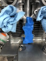
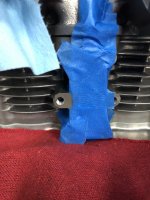
When I was installing the cam chain tensioner cover, I totally screwed up and misread the torque specs on the bolts. I stripped the hell out of one of them. I was simultaneously angry and terrified at what I had done as this was a tapped hole in the jug... Luckily I happened upon a thread here about the magic of Helicoils. I got a kit and was actually amazed at how easy it was to repair and how _good_ the tap felt. Only set me back a few days and you could imagine my relief.


Next up was the shift shaft, all cleaned up. I didn't take good pictures, but it's key to use the flathead adjusting screw (shown in 'starter gear' pics below) to get the two 'fingers' of the shift arm centered across the shifter star. That's a horrible explanation, but the manual explains it well, and you can see the centered positioning of the shift star within these two fingers in the pic below:


Starter gears:

Primary drive gears:

Clutch boss, plates and top plate (Phillips heads replaced with allen bolts when I first got the bike)

Kickstarter, with new spring shown, although I should say I got this spring from Mike's and I hated it, and put the original back on. The action felt clumsy and sort of like it was binding on the return.


Other side....new 17T stock replacement sprocket:


You'll note I kept the original chain guard/guide....It was a little worn, but I thought it would hold up ok. Honestly, I would have replaced it if I could find another. Has anyone ever seen these around?
And my HHB rotor/stator/source coil back on:

You can see in one of the pics above I also put the points/advance covers back on, but left the tappets off, for obvious reasons until I adjust. So that's pretty much it for the main motor! Crazy!! It probably took about 3-4 months, and most of that was because 1) I was super anal about cleaning, 2) I researched every step several times to make sure I knew what I was doing and to avoid the non-obvious pitfalls that you can only find in resources like this forum.
Anyone bored of this motor? I'm getting tired of talking about it haha. Now it was time to button up the last bits on the motor.
Breather cover (two-hose style). I've been reading a lot about this lately, some really good threads on different breather options and the evolution over the life of the XS. I opted to keep my 'double-snorkel" style. To remind folks; the 74 breather was just two open hoses, with no restriction plug or anything. These were not the ones that fed back into the airbox or anything like that.
Funny story.... When I first got the bike, I had always noticed two thick black rubber hoses running down from between the carbs into a tube that was tucked between the center upright frame member and the swingarm. Me, not knowing a whole lot about motorcycles, doesn't really question the function...I have a vague concept of crankcase breathers and venting and assume it's some sort of filtration unit. When I broke the bike down for this rebuild and pull this thing out, I realized that it was a shampoo bottle that the PO had cut the top off of and spray painted black
. I guess the good thing was that there wasn't really anything in it haha When I was installing the cam chain tensioner cover, I totally screwed up and misread the torque specs on the bolts. I stripped the hell out of one of them. I was simultaneously angry and terrified at what I had done as this was a tapped hole in the jug... Luckily I happened upon a thread here about the magic of Helicoils. I got a kit and was actually amazed at how easy it was to repair and how _good_ the tap felt. Only set me back a few days and you could imagine my relief.
Next up was the shift shaft, all cleaned up. I didn't take good pictures, but it's key to use the flathead adjusting screw (shown in 'starter gear' pics below) to get the two 'fingers' of the shift arm centered across the shifter star. That's a horrible explanation, but the manual explains it well, and you can see the centered positioning of the shift star within these two fingers in the pic below:
Starter gears:
Primary drive gears:
Clutch boss, plates and top plate (Phillips heads replaced with allen bolts when I first got the bike)
Kickstarter, with new spring shown, although I should say I got this spring from Mike's and I hated it, and put the original back on. The action felt clumsy and sort of like it was binding on the return.
Other side....new 17T stock replacement sprocket:
You'll note I kept the original chain guard/guide....It was a little worn, but I thought it would hold up ok. Honestly, I would have replaced it if I could find another. Has anyone ever seen these around?
And my HHB rotor/stator/source coil back on:
You can see in one of the pics above I also put the points/advance covers back on, but left the tappets off, for obvious reasons until I adjust. So that's pretty much it for the main motor! Crazy!! It probably took about 3-4 months, and most of that was because 1) I was super anal about cleaning, 2) I researched every step several times to make sure I knew what I was doing and to avoid the non-obvious pitfalls that you can only find in resources like this forum.
Attachments
Oil pump:
Made the unfortunate discovery that one of the rotors of my oil pump was cracked. I guess of all things to find inside the motor, this ain't so bad.

Luckily, I found a used oil pump on EBay for $15, that I could just take the two rotor from (seemed a good idea to replace as a pair). Cleaned up, and reassembled:


Made the unfortunate discovery that one of the rotors of my oil pump was cracked. I guess of all things to find inside the motor, this ain't so bad.
Luckily, I found a used oil pump on EBay for $15, that I could just take the two rotor from (seemed a good idea to replace as a pair). Cleaned up, and reassembled:
We’re all gear heads here, of course we’re not tired of your engine build! Haha! 
That’s too funny about the shampoo bottle catch can. I have the same style breather as you, as you seem to already know , as the years passed they tried a number of variations of breather styles, eventually restricting the openings and the number of outlets in an attempt to reduce oil vapor and mess under the motor and frame. On mine, I epoxied a couple of nuts inside the breather tubes to restrict the opening size.

Some guys attach pvc or one way brake check valves to the breather hoses to stop vapor drips. I get a little dripping after going for a ride. When I get home and park my bike, I just slip a piece of newspaper under the bike to catch a couple drips. Once it cools off it doesn’t drip anymore.
That’s too funny about the shampoo bottle catch can. I have the same style breather as you, as you seem to already know , as the years passed they tried a number of variations of breather styles, eventually restricting the openings and the number of outlets in an attempt to reduce oil vapor and mess under the motor and frame. On mine, I epoxied a couple of nuts inside the breather tubes to restrict the opening size.
Some guys attach pvc or one way brake check valves to the breather hoses to stop vapor drips. I get a little dripping after going for a ride. When I get home and park my bike, I just slip a piece of newspaper under the bike to catch a couple drips. Once it cools off it doesn’t drip anymore.
This is a great thread for sure. I may even tackle the spare engine I have just sitting. JC
Well shoot, I'll keep going then! God knows I've got the pictures haha.
I also love how there's rarely consensus on 'absolute best' on any of these topics on this forum. I've mentioned before I'm relatively inexperienced with small engine repair, but I have a good mechanical aptitude and this forum is the best education in the Yamaha 650 you could ever ask for. I like how if you have a simple question, you can probably find a simple answer. I like if you have a not so simple question, you can find a lot of well thought out opinions, which is exactly the kind of thing I need to become informed enough to determine a path forward of my own.
Good example - for my breather I decided the best solution for me was to keep the double snorkel, take two ~3" lengths of the black thin-walled breather tubing, loosely pack with some 0000 steel wool I had to act as a oil 'condensation media' if you will, and then terminate each with one of the power brake valves that have been referenced on here many time. So they're just hanging out between the carb tops and I will keep a close eye (and finger) in the open ends of those valves to see if any oil is getting through. Maybe I'll post this over in the breather section after testing a little. I'll post pics shortly, I don't have any handy (for once).

Nice solution Bob. Yes, I actually just sorted mine out last week....it was one of the last things I had to figure out (and not one I fully appreciated the varied opinions on). I read the couple threads on here discussing the evolution of them and the pros/cons of the different approaches. One of the things I love about this bike is learning about the history and nuances of the evolution of the design year-to-year and how clearly Yamaha was learning these things too and responding. So whereas clearly some elements of the motor design were quite good, even from the get-go, there were clearly areas they were continuously struggling to pin down through the production period (this breather, tappet clearances, cam chain tensioner damper all jump to mind immediately).On mine, I epoxied a couple of nuts inside the breather tubes to restrict the opening size.
I also love how there's rarely consensus on 'absolute best' on any of these topics on this forum.
I've mentioned before I'm relatively inexperienced with small engine repair, but I have a good mechanical aptitude and this forum is the best education in the Yamaha 650 you could ever ask for. I like how if you have a simple question, you can probably find a simple answer. I like if you have a not so simple question, you can find a lot of well thought out opinions, which is exactly the kind of thing I need to become informed enough to determine a path forward of my own.Good example - for my breather I decided the best solution for me was to keep the double snorkel, take two ~3" lengths of the black thin-walled breather tubing, loosely pack with some 0000 steel wool I had to act as a oil 'condensation media' if you will, and then terminate each with one of the power brake valves that have been referenced on here many time. So they're just hanging out between the carb tops and I will keep a close eye (and finger) in the open ends of those valves to see if any oil is getting through. Maybe I'll post this over in the breather section after testing a little. I'll post pics shortly, I don't have any handy (for once).
Well hot damn Superjet, thanks a million, and definitely go for it! As I've been posting all this, it sort of feels like I'm rehashing a lot of stuff that's already out there, so if this is providing any sort of fresh look at this, then it's all worth it for meThis is a great thread for sure. I may even tackle the spare engine I have just sitting.
Last edited:
That’s too funny about the shampoo bottle catch can.
When I rebuilt a Triumph TR6 650 twin some 3 or 4 years ago, decided to fit a spin-on oil filter. This meant cutting in to the return oil line and adding a filter mount. But where to, uhm, mount the mount? Explored various options. The solution eventually adopted was to place the filter mount behind the frame down tube, below the battery box, accessible by removing the l/h side-cover. Securely held on by hose clips. In a rubber-lined sweetcorn tin.
Well?
. . . this forum is the best education in the Yamaha 650 you could ever ask for . . .
I concur.
Carbs:
When I bought the bike in 2018 one of the first things I did was a carb rebuild, because even though the bike ran, it seemed like it couldn't hurt. I knew the bike had been sitting for the previous ~15 years and while the interior of the tank was really clean, it just seemed prudent to open them up, clean them out and replace the jets while I was in there. I don't know that I would do the same now over just cleaning, but, hey, it's what I did
This bike's got the original BS38 Mikuni carbs. Not much to say, I'll throw some pics up of my original rebuild here. As you can see, the insides were pretty gross, and my spray carb cleaner/little brush technique was kind of effective to clean them up, just a bit. Took a lot of pics here to make sure the jets were comparable in the replacement set. Goal was not to change the jets here versus stock.


Good news was that this seemed to be effective, bike ran pretty well for the couple months I had it on the road last year. Was pleasantly surprised to find the diaphragms were in good health and intact after learning how those are pretty tricky (or at worst, expensive) to come by.
So during this resto, I wanted to give them a reeeeeally good cleaning in the vapor blaster. Before I post the reassembled pics, I should note that I took this opportunity to give my brass floats an actual functional test, which I would heavily advocate for as it was super effective. Filled an old glass pickle jar with near-boiling water and submerged the floats holding with a pair of needlenose pliers so I could move and examine while submerged. Idea is the hot water quickly heats the air in the floats and will give you a visual indication if your floats are leaky with a stream of bubbles. If you DO have a hole/leak (like I did in both floats!) you can repeat the process after the float cools down, with the hole facing down, the air expansion will have the added benefit of pushing any remaining gas in the float out of the hole. So I did this procedure and just lightly soldered over my holes and retested w/ hot water. No leaks!! Beautiful. Saved myself some pretty pricey new brass floats, or some cheaper plastic replacements. There are some great how-to's on this out there (I'm paraphrasing). You need to open and reseal the factory vent holes to do this but it's all pretty easy and took less than an hour for both floats.


Some "carb porn", for your Saturday morning, haha:


When I bought the bike in 2018 one of the first things I did was a carb rebuild, because even though the bike ran, it seemed like it couldn't hurt. I knew the bike had been sitting for the previous ~15 years and while the interior of the tank was really clean, it just seemed prudent to open them up, clean them out and replace the jets while I was in there. I don't know that I would do the same now over just cleaning, but, hey, it's what I did
This bike's got the original BS38 Mikuni carbs. Not much to say, I'll throw some pics up of my original rebuild here. As you can see, the insides were pretty gross, and my spray carb cleaner/little brush technique was kind of effective to clean them up, just a bit. Took a lot of pics here to make sure the jets were comparable in the replacement set. Goal was not to change the jets here versus stock.
Good news was that this seemed to be effective, bike ran pretty well for the couple months I had it on the road last year. Was pleasantly surprised to find the diaphragms were in good health and intact after learning how those are pretty tricky (or at worst, expensive) to come by.
So during this resto, I wanted to give them a reeeeeally good cleaning in the vapor blaster. Before I post the reassembled pics, I should note that I took this opportunity to give my brass floats an actual functional test, which I would heavily advocate for as it was super effective. Filled an old glass pickle jar with near-boiling water and submerged the floats holding with a pair of needlenose pliers so I could move and examine while submerged. Idea is the hot water quickly heats the air in the floats and will give you a visual indication if your floats are leaky with a stream of bubbles. If you DO have a hole/leak (like I did in both floats!) you can repeat the process after the float cools down, with the hole facing down, the air expansion will have the added benefit of pushing any remaining gas in the float out of the hole. So I did this procedure and just lightly soldered over my holes and retested w/ hot water. No leaks!! Beautiful. Saved myself some pretty pricey new brass floats, or some cheaper plastic replacements. There are some great how-to's on this out there (I'm paraphrasing). You need to open and reseal the factory vent holes to do this but it's all pretty easy and took less than an hour for both floats.
Some "carb porn", for your Saturday morning, haha:
In a rubber-lined sweetcorn tin.
Well?
Haha, Raymond you will get NO judgments from me!! Clearly the shampoo bottle was effective and had been working for at least 20 years.
Carbs came out very nice!
Wheels:
After a season of trying to polish up 40+ year old rusty spokes, I decided to rebuild the wheels and replace the original spokes with stainless. Since I was going through the trouble, I figured I'd take the opportunity to replace the wheel bearings and seals. And since I was doing THAT, I might as well clean up the front hub/rear drum. In breaking down the wheels, first was pulling off the tires (before I knew I would be doing this rebuild, I regrettably put on a fresh set of tires for what ended up just being a couple rides. What a waste of a mount and balance!) and then removing the old spokes.


Then, knocked out the old bearings and spacers


And vapor blasted the hubs and drum:


I had a whole process with the rims. My rims were in decent shape. Good, not great. Some pits. I thought I would try to buff them out. I spent the better part of a Saturday wet sanding, by hand, with a ridiculous regiment of 180/320/600/800/1200/1500/2000/3000 paper. At the end they looked really good! Except for the *#$)%#* pits that I missed. Can't see in the pics so much, but they're there!!! And it was heartbreaking, hahah.


So I don't know, I've seen some really awesome results here of guys that can do these amazing mirror finishes by hand, starting from what seems like a block of aluminum ORE. For me, it sucked and it was demoralizing to think of doing another wheel. So (I'll be honest here) - I caved..... Since I was already working with my powder folks at this point, I found some really nice silver from Prismatic (BMW Silver, FYI), that I thought would complement the satin finish on the hub/drum. So I totally took the easy route and had them powdered. I actually think they came out great, but it felt like a bit of a cop-out heh.


I installed the new bearings/spacers (I won't rehash, a lot of really good threads here). Only comment on bearings is make sure they are all FULLY seated. One trick I found handy if you don't have bearing drivers is to use the old bearings to drive the new ones in....although make sure you either sand a bit off, or cut the outer race with a grinder or something so that it doesn't get stuck in the hub. Do NOT ask me how I know...
Then it was rebuild time. I have never built a wheel, and was certainly something that was intimidating before I tried. I have to say, the process wasn't bad at all, if you take your time and understand the spoke pattern. I found some great resources here, as well as some other websites that I'd be glad to point to. I put the steps of the process below:


I think the rim/spokes/hub actually look very sharp together, and I was very pleased with the final product.
As for trueing.....a lot of good knowledge on the web about this, and what I'll say is that I found a lot of it is indeed feel for how a wheel will respond to a tighten/loosen on a spoke. But long story short....you CAN true your own wheels with not much more than a couple of jack stands and a cheap dial gauge from Harbor Freight. A picture of my DIY rig using the wheel axle, and a video below illustrating the radial run-out well within spec.

After a season of trying to polish up 40+ year old rusty spokes, I decided to rebuild the wheels and replace the original spokes with stainless. Since I was going through the trouble, I figured I'd take the opportunity to replace the wheel bearings and seals. And since I was doing THAT, I might as well clean up the front hub/rear drum. In breaking down the wheels, first was pulling off the tires (before I knew I would be doing this rebuild, I regrettably put on a fresh set of tires for what ended up just being a couple rides. What a waste of a mount and balance!) and then removing the old spokes.
Then, knocked out the old bearings and spacers
And vapor blasted the hubs and drum:
I had a whole process with the rims. My rims were in decent shape. Good, not great. Some pits. I thought I would try to buff them out. I spent the better part of a Saturday wet sanding, by hand, with a ridiculous regiment of 180/320/600/800/1200/1500/2000/3000 paper. At the end they looked really good! Except for the *#$)%#* pits that I missed. Can't see in the pics so much, but they're there!!! And it was heartbreaking, hahah.
So I don't know, I've seen some really awesome results here of guys that can do these amazing mirror finishes by hand, starting from what seems like a block of aluminum ORE. For me, it sucked and it was demoralizing to think of doing another wheel. So (I'll be honest here) - I caved..... Since I was already working with my powder folks at this point, I found some really nice silver from Prismatic (BMW Silver, FYI), that I thought would complement the satin finish on the hub/drum. So I totally took the easy route and had them powdered. I actually think they came out great, but it felt like a bit of a cop-out heh.
I installed the new bearings/spacers (I won't rehash, a lot of really good threads here). Only comment on bearings is make sure they are all FULLY seated. One trick I found handy if you don't have bearing drivers is to use the old bearings to drive the new ones in....although make sure you either sand a bit off, or cut the outer race with a grinder or something so that it doesn't get stuck in the hub. Do NOT ask me how I know...
Then it was rebuild time. I have never built a wheel, and was certainly something that was intimidating before I tried. I have to say, the process wasn't bad at all, if you take your time and understand the spoke pattern. I found some great resources here, as well as some other websites that I'd be glad to point to. I put the steps of the process below:
I think the rim/spokes/hub actually look very sharp together, and I was very pleased with the final product.
As for trueing.....a lot of good knowledge on the web about this, and what I'll say is that I found a lot of it is indeed feel for how a wheel will respond to a tighten/loosen on a spoke. But long story short....you CAN true your own wheels with not much more than a couple of jack stands and a cheap dial gauge from Harbor Freight. A picture of my DIY rig using the wheel axle, and a video below illustrating the radial run-out well within spec.
Wheel building? Your first bike? Respect.
SomervilleXS650, it is never a cop-out when you get results that are excellent +++.
Very nice!!!
Very nice!!!
I’ve seen guys powder coat their wheels a gloss black, but I’ve never seen a satin silver finish on them, I think they came out great. Regarding polishing......take it from a guy who got a little obsessive over it, this whole satin finish look you’ve got going is not only something that will make your bike stand out from the rest, it will be easier to maintain as well. I like it!
Thanks guys! The maintenance thing was a happy accident, I am hoping it's a bit easier to keep looking sharp over a high-polish. Time will tell...
Instrument panel:
If you have/had a stock XS/TX from this era, there's a decent chance you either 1) broke the instrument gauge bracket or 2) it was broken when you got it. In my case, it was #2. Some PO along the way had dropped the bike. The front fender was cockeyed and had a split where it had rolled in, the tank had a few dents in one area on the LH side and was missing a bit of paint, and the gauge mount bracket was cracked on the LH side. For those unfamiliar, the bracket is sort of shaped like a pair of eyeglasses; cast aluminum with rings on either side of the central indicator lights and ignition. The speedo and tach each sit in one of the rings. While aesthetically I think it's great, the problem is the rings are prone to cracking, and I imagine it must be in a prone area if the bike is dropped, because like 3 of 4 that I found on Ebay are broken in this way (including one I bought where this defect was hidden very well in the pics....luckily the seller was reasonable and agreed to accept a return). Also, ones that you find often have a common defect where the paint is worn away under the ignition, obviously from other keys vibrating/scratching. So mine was really unusable in the current state, at least for me as I don't have a TIG welder., and while I had tried an epoxy fix, with a bit of aluminum 'scab' to sit across the joint for additional substrate, this was a temporary fix and was re-cracked when I broke the bike down. So I was looking for a replacement.
What I'll say is that if you look for a direct replacement there's a good chance they're also broken, and if they're not they're probably relatively expensive. By doing a little research and with a little luck, I found one from a TX500 for only $30. The mount holes were the same so it was a direct swap, and my gauges fit in there perfectly.

Something to note about this bracket is that the plastic indicator lenses mount into recesses in the bracket, and there is a thin aluminum fascia panel that sits over the lenses and sandwiches them in. This fascia panel was originally painted a similar color to the body paint (a little hard to tell with the age) and has the labels for the indicator lights stenciled on there. I carefully pried away the fascia panel. The problem with this panel is it is SUPER thin, so it gets dinged up with wear/age so I knew that if I just painted it, it would still look sort of ratty.

I decided I would try to powder coat it in gloss black with a small Eastwood set-up I bought with a buddy when I first got the bike. BTW, for the record, I LOVE this kit for smalls. I bought a cheap toaster oven and it's so handy to prep/coat parts in like an hour. In order to smooth out the fascia plate and give a smooth/consistent finish to the panel, I took a high-temp epoxy putty (because I was powder coating and needed to bake at 400F) and did a 'skim-coat' of sorts. You can see the powder coated bracket (without fascia panel) mocked up with the gauges and ignition here:

and you can see me mocking the fascia up over the powder coated bracket.


I then powder coated the fascia panel, and the results came out pretty nice. Now - for the labeling.... I have a good friend who is a graphic designer and does freelance signage. Why is this useful? Because this means I have access to a vinyl cutter! I found a font that emulated the original text pretty well, and did a little Photoshop work to make a file to send over to my buddy. A couple days later, I received my white vinyl letters in the mail and transferred them to the fascia. Looking pretty good!

I then did a few layers of rattle-can clear coat over the whole thing to seal it.

You'll see I added a cool little tri-fork logo in the middle. I also added one additional feature that is pretty cool; a battery voltage indicator. This is the Eclipse 8 from Sparkbright (https://www.sparkbright.co.uk/index.php). Really cool little device that gives a voltage reading with a single LED by changing color. I've had elec issues previously, and while I'm quite confident in my electrical and charging now (I have much more electrical experience than mechanical), being burned will leave you a little gunshy hahaha, so figured this thing was a great insurance policy. Highly recommend, was like $20 from the UK and very easy to wire in. Only regret, which I'm sure many of you keen-eyed folks noticed and are probably far too polite to point out is that the mounting hole for the indicator is slightly off-center. DANG IT!!
I bought some new cushion gasketing to put around the gauges to secure them against vibration and movement (forget the company now, but has been discussed on this forum before). Final gauge assembly here:

Even with my screw-up on the V+ indicator.....I love how this came out, probably one of the most rewarding parts of the build, since the solution I ultimately came up with took a little creativity.
If you have/had a stock XS/TX from this era, there's a decent chance you either 1) broke the instrument gauge bracket or 2) it was broken when you got it. In my case, it was #2. Some PO along the way had dropped the bike. The front fender was cockeyed and had a split where it had rolled in, the tank had a few dents in one area on the LH side and was missing a bit of paint, and the gauge mount bracket was cracked on the LH side. For those unfamiliar, the bracket is sort of shaped like a pair of eyeglasses; cast aluminum with rings on either side of the central indicator lights and ignition. The speedo and tach each sit in one of the rings. While aesthetically I think it's great, the problem is the rings are prone to cracking, and I imagine it must be in a prone area if the bike is dropped, because like 3 of 4 that I found on Ebay are broken in this way (including one I bought where this defect was hidden very well in the pics....luckily the seller was reasonable and agreed to accept a return). Also, ones that you find often have a common defect where the paint is worn away under the ignition, obviously from other keys vibrating/scratching. So mine was really unusable in the current state, at least for me as I don't have a TIG welder., and while I had tried an epoxy fix, with a bit of aluminum 'scab' to sit across the joint for additional substrate, this was a temporary fix and was re-cracked when I broke the bike down. So I was looking for a replacement.
What I'll say is that if you look for a direct replacement there's a good chance they're also broken, and if they're not they're probably relatively expensive. By doing a little research and with a little luck, I found one from a TX500 for only $30. The mount holes were the same so it was a direct swap, and my gauges fit in there perfectly.
Something to note about this bracket is that the plastic indicator lenses mount into recesses in the bracket, and there is a thin aluminum fascia panel that sits over the lenses and sandwiches them in. This fascia panel was originally painted a similar color to the body paint (a little hard to tell with the age) and has the labels for the indicator lights stenciled on there. I carefully pried away the fascia panel. The problem with this panel is it is SUPER thin, so it gets dinged up with wear/age so I knew that if I just painted it, it would still look sort of ratty.
I decided I would try to powder coat it in gloss black with a small Eastwood set-up I bought with a buddy when I first got the bike. BTW, for the record, I LOVE this kit for smalls. I bought a cheap toaster oven and it's so handy to prep/coat parts in like an hour. In order to smooth out the fascia plate and give a smooth/consistent finish to the panel, I took a high-temp epoxy putty (because I was powder coating and needed to bake at 400F) and did a 'skim-coat' of sorts. You can see the powder coated bracket (without fascia panel) mocked up with the gauges and ignition here:
and you can see me mocking the fascia up over the powder coated bracket.
I then powder coated the fascia panel, and the results came out pretty nice. Now - for the labeling.... I have a good friend who is a graphic designer and does freelance signage. Why is this useful? Because this means I have access to a vinyl cutter! I found a font that emulated the original text pretty well, and did a little Photoshop work to make a file to send over to my buddy. A couple days later, I received my white vinyl letters in the mail and transferred them to the fascia. Looking pretty good!
I then did a few layers of rattle-can clear coat over the whole thing to seal it.
You'll see I added a cool little tri-fork logo in the middle. I also added one additional feature that is pretty cool; a battery voltage indicator. This is the Eclipse 8 from Sparkbright (https://www.sparkbright.co.uk/index.php). Really cool little device that gives a voltage reading with a single LED by changing color. I've had elec issues previously, and while I'm quite confident in my electrical and charging now (I have much more electrical experience than mechanical), being burned will leave you a little gunshy hahaha, so figured this thing was a great insurance policy. Highly recommend, was like $20 from the UK and very easy to wire in. Only regret, which I'm sure many of you keen-eyed folks noticed and are probably far too polite to point out is that the mounting hole for the indicator is slightly off-center. DANG IT!!
I bought some new cushion gasketing to put around the gauges to secure them against vibration and movement (forget the company now, but has been discussed on this forum before). Final gauge assembly here:
Even with my screw-up on the V+ indicator.....I love how this came out, probably one of the most rewarding parts of the build, since the solution I ultimately came up with took a little creativity.
Very nicely done!