73 TX650 Boyer Bransden Kit 00303 fitting: extra wires!

TX650Jim

XS650 Member
Messages
13
Reaction score
2
Points
3
Location
Wolverhampton, UK
Hi all,
Before you all groan and say this has been done to death, please just take a deep breath and see if you can help me out.
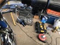
I have made a start fitting the kit following the instructions provided but find them a bit misleading, there is no instructions on what to do with your current wiring, only how to connect up your new kit.
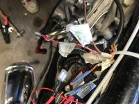
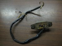
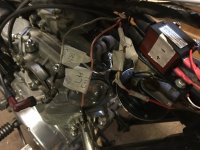
I will upload some pics and see if you can advise,... I have on the left side a grey and orange wire still hooked up to the black wires coming from the condenser, they both originally had the corresponding Orange and grey wires from the points stator also connected to them.
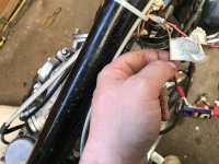
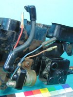
On the right side I had written labels indicating where the wires had come from, again both grey and orange wires, the grey one coming from the loom marked as connected to right hand coil to the orange wire. The other loose orange one, also from the loom marked as connected to the left hand coil with an orange connection wired.
If you are now confused, join the club.
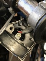
If we can sort that bit out 1st I’ll move onto the next dilemma. I wondered if the Condenser still performs any function with the new setup, If not, should these wires just be blanked off or connected together?
There is no instruction on this so thought it best to ask rather than fry something.
Jim
 

Attachments

  • image.jpg
    image.jpg
    122.2 KB · Views: 211
  • image.jpg
    image.jpg
    151.9 KB · Views: 200
  • image.jpg
    image.jpg
    146.4 KB · Views: 236
Last edited:
The thread by Runnriot should answer your questions as there is no difference in ignition wiring between 1973 and 1976, but here it is again. The breaker point and condenser wiring is not used with the BB system and can be removed or left in place as you see fit. The BB igniter box controls the spark. Crimp a double socket connector on the R/W wire from the kill switch, crimp plug (bullet) connectors on the red wire from the BB box and the wire to the the + terminal of the coil, and plug both of the bullet connectors into the R/W double socket so that the R/W wire delivers power to the box and to the + terminal of the coil. Connect the black wire from the box to the - coil terminal; this is the wire that interrupts the ground connection of the coil primary windings and causes the current to seek ground through the secondary coil windings and spark plugs, just as the points did previously. Crimp a ring connector on the white wire from the box and ground it to the frame, then connect the timing plate wires to the matching wires from the box.
 
Thanks grizld1,
It is my first post up on here so still trying to find my way around. I’ll made a search on Runnriot... I thought as much about the condenser but the info supplied had no reference. My bike has an electric start, I’m not sure they all had the same system. I’ll go through what you have written check out Runnriot and see where it gets me. Every connection in the diagram is obviously straight forward, it’s just what was left out that’s concerned me. If you are handy with electrics fairplay, my knowledge is limited, but if you don’t have a go, you’ll never learn mate.
Cheers, Jim
Yeah were in the same boat, we were left with wires and not knowing what to do with them. Turns out we dont need the orange and gray wire so i ended up covering the wires up with heat shrink tubing. I put 1 on first to cover the entire end of the wire with about 1/2" left over, i bent the left over back towards the wire and then heat shrinked another tube over those to provide a more water proof and sealed connection.

As for the Red/White wire. It had me confused because i wasnt sure how to properly connect 2 new wires into 1, but turns out I had to buy a Double Female Bullet Connector , which not many places sell. I ordered it online yesterday, hopefully it ships tomorrow but most likely i wont have them till next week.

Aside that im trying to figure out the best spot for the Blue box, and the new coil, i already drilled new holes in the old coil brackets but need to make sure once i add the coil and blue box i will have room for the two devices i removed (one in the middle of the frame that was above the coil held up with a rubber tube the other was int he slot in front where i will put the blue box. I think both can fit somewhere on the right side old coil plate, I just need to make sure the gas tank can properly fit back on over everything.


upload_2020-9-16_14-31-31.png
 
Also, see my link below of some progress photos of the work as well as theres a documents file in there with useful links to browse thru that will help. Two of them have pretty decent step by step images.

Took me a while to find what i was looking for in the forums so i think this might help others as well.
https://www.dropbox.com/sh/0q5hfcf7o55h7sg/AAAiPnbaG-Y9JTow6gNh6zXka?dl=0
 
Hi Runriot, The info on blanking the grey and orange wires off, did you get that from Boyer or has some one told you this? Have they done this conversion before? It is the first I’ve heard to blank them off, I kind of guessed it might be the case but as they are sill connected at the other end of the loom I wanted to make sure they were not still live or would interfere in any way. I feel a bit further down the road than you, I only need to know what to do with these wires, the rest is hooked up and ready to go.
 
Hi Runriot, The info on blanking the grey and orange wires off, did you get that from Boyer or has some one told you this? Have they done this conversion before? It is the first I’ve heard to blank them off, I kind of guessed it might be the case but as they are sill connected at the other end of the loom I wanted to make sure they were not still live or would interfere in any way. I feel a bit further down the road than you, I only need to know what to do with these wires, the rest is hooked up and ready to go.
See my thread, I asked the same question and was told they are no longer needed and can be left alone so i decided to just 'cap' the wires so they arent touching any other wires when bare in case they are live. Hopefully this is the proper way to do it....

http://www.xs650.com/threads/76-xs-boyer-ignition-install-wiring.58283/#post-661991
 
Hi Runriot, The info on blanking the grey and orange wires off, did you get that from Boyer or has some one told you this? Have they done this conversion before? It is the first I’ve heard to blank them off, I kind of guessed it might be the case but as they are sill connected at the other end of the loom I wanted to make sure they were not still live or would interfere in any way. I feel a bit further down the road than you, I only need to know what to do with these wires, the rest is hooked up and ready to go.
Feel free to post some photos of where you installed the blue box and new coil so myself and others can also see what options we have.
 
I will do, thanks, yes you and I are having exactly the same dilemmas, I just haven’t read anywhere else to blank off wires, I just want to be sure that we are definitely going down the right route. I do not have a red wire with white added, my red/white stripe wire I think goes directly to the ignition switch, from my continuity test... my bike is a TX650 from 73, I understand that it is the same as an XS2,... or very similar. Your bike looks like a later model, although the kit does state that it covers many years through the XS manufacture.
 
I will do, thanks, yes you and I are having exactly the same dilemmas, I just haven’t read anywhere else to blank off wires, I just want to be sure that we are definitely going down the right route. I do not have a red wire with white added, my red/white stripe wire I think goes directly to the ignition switch, from my continuity test... my bike is a TX650 from 73, I understand that it is the same as an XS2,... or very similar. Your bike looks like a later model, although the kit does state that it covers many years through the XS manufacture.
Mine is a Red wire with white line/stripe (seems like same wire as yours). Per Wiring diagrams for TX650 and for my 76' 650D this wire goes directly to the Engine Stop Switch/Kill switch. The kill switch looks to be wired to the ignition switch. So to my understanding we are connecting to the correct wire.

Let me know if you need a picture of the wiring diagram for a TX650. I have the Clymer book which is for models 1970-1982
 
You may, (possibly), find there is a G/Y wire from the front brake switch joining to the Y wire on the rear brake switch

We didn't find a R/W in the ignition as per the Clymer manual, wiring diagram..............Br (power),from ignition to engine stop, R/W out to coils,

Thread on making up the diagram.........Mailman posted a lot of pics in post #72- #74
http://www.xs650.com/threads/72xs2-73tx-wiring-diagram.53244/
 
Feel free to post some photos of where you installed the blue box and new coil so myself and others can also see what options we have.

Here you go, I’ve done what most do I think, although I used the hole nearest the rear instead of the front like others. I figured the space gets narrower towards the front. Drilled an extra hole in the metal supporting bracket. I used two 1/2” nylon spacers, then thread locked the bolts through for good measure. I haven’t made a permanent fix on my blue box as yet, figured making sure everything ran ok was probably a wise move. I recoated the inside of my tank and replaced the diaphragms in the carbs at the same time.

image.jpg
image.jpg
image.jpg
 
Last edited:
The thread by Runnriot should answer your questions as there is no difference in ignition wiring between 1973 and 1976, but here it is again. The breaker point and condenser wiring is not used with the BB system and can be removed or left in place as you see fit. The BB igniter box controls the spark. Crimp a double socket connector on the R/W wire from the kill switch, crimp plug (bullet) connectors on the red wire from the BB box and the wire to the the + terminal of the coil, and plug both of the bullet connectors into the R/W double socket so that the R/W wire delivers power to the box and to the + terminal of the coil. Connect the black wire from the box to the - coil terminal; this is the wire that interrupts the ground connection of the coil primary windings and causes the current to seek ground through the secondary coil windings and spark plugs, just as the points did previously. Crimp a ring connector on the white wire from the box and ground it to the frame, then connect the timing plate wires to the matching wires from the box.
Just about to have a look this morning. One wire that hasn’t been mentioned is the brown one from the electric starter lever. I have done a continuity from the lever, it would appear the other end comes out of the loom by where the coils were, I have it labelled previously as connected to coils. I take it this wire should be connected to the pos + group of wires as well, making a 4way connection block opposed to 3. My only concern is that it would be live even if the kill switch was turned to off. Not that I would be pulling the lever once it was started but you imagine that the kill switch should override all connections to +.

image.jpg
 
The way we worked it out was the power from ignition to kill switch comes in on the brown, out on red/white to coils........back on brown to safety relay, out of safety relay on brown to solenoid.......out of solenoid on Blue/white to ignition lever. ..........no power out of ignition lever till level is pulled.........when engine engages the power on Yellow to starter relay triggers relay to cut out starter..........

There is no brown on electric starter lever. That brown is power to kill switch, then out on Red/White.
d779138c-9cee-4112-80df-6ebad9554429-jpeg.135776


Is yours different????
 
This brown wire has continuity between it and the starter lever wire and both the starter solenoid
 

Attachments

  • image.jpg
    image.jpg
    157 KB · Views: 185
  • image.jpg
    image.jpg
    170.7 KB · Views: 187
Last edited:
The Kill switch inside casing has brown and another red/w the same as your pic. This leads down to the other free wire r/w, coming from the loom and shows continuity in run position, but not kill, so definitely power from there...
 

Attachments

  • image.jpg
    image.jpg
    166.7 KB · Views: 188
  • image.jpg
    image.jpg
    176.3 KB · Views: 186
Last edited:
The way we worked it out was the power from ignition to kill switch comes in on the brown, out on red/white to coils........back on brown to safety relay, out of safety relay on brown to solenoid.......out of solenoid on Blue/white to ignition lever. ..........no power out of ignition lever till level is pulled.........when engine engages the power on Yellow to starter relay triggers relay to cut out starter..........

There is no brown on electric starter lever. That brown is power to kill switch, then out on Red/White.
d779138c-9cee-4112-80df-6ebad9554429-jpeg.135776


Is yours different????
Isn’t it just these two wires? Although I do not know where to wire the brown...

224F5B2C-CF4E-4700-84B6-AF622A259D79.jpeg
 
Red/white wire isn't connected, has a non factory bullet connector. That wire on Factory harnesses is co joined with the brown wire, not in a double connector.......
img_20181016_160400-jpg.127795


Starter relay has 2 brown wires. One feeding into it, (from co-joined red/white going to coils), and another going out to the starter solenoid...........
120364-880c2bb84b6e879515653cee4ec01f4b.jpg
120362-8a0cd2e9de20216b6a6ce8af0328f215.jpg
 
Back
Top