Keep you warm, I'll bet.
-
Enjoy XS650.com? Consider making a donation to help support the site.
XS650.com receives a small share of sales from some links on this page, but direct donations have a much greater impact on keeping this site going.
You are using an out of date browser. It may not display this or other websites correctly.
You should upgrade or use an alternative browser.
You should upgrade or use an alternative browser.
Stuff my dog says; on second thought I'll just build a race car
- Thread starter NashGTI
- Start date
When I'm thinking cigar bodied F1 I am thinking the rear engine stuff. This Eagle is a beautiful example.

My desire is to do something like that with a high revving Ford 302, hopefully with a flat crank, driving through a Porsche transaxle and using an 8 stack fuel injection. Way more complex and costly than one of the front engined cars. I've always seen that particular time to be the pinnacle of cool of racing, which is pretty close to the pinnacle of cool of just things to do at all so I'd love to be able to do one.
As for where do you sit in a front engined single seater, there were two schools of thought. One was that you simply straddle the driveshaft with pedals on either side of the transmission. You can see that one this picture which if I remember is an old Alfa.

The other was that you offset the engine and transmission off to one side of the chassis and then sit on the other. The overhead shot of the Delage shows this well. It was especially popular once they learned to start laying the engine over to lower the center of gravity as opposed to just sitting the engine straight up and down like we think of old inline engine cars and trucks. Our intention was to offset the driveline to the right hand side with all of us being used to right hand shift and then sit to the left. It makes the shifter easier and with the Tornado engine it just makes more sense because the alternator and intake side are on the left with the exhaust and distributor on the right.
Something else to keep in mind that just seems wrong when you read it is that these were big cars. The wheelbase and track width on the Delage is basically the side of a Jeep CJ7. The track is about a half inch narrower and the wheelbase on the Delage is actually a few inches longer than the CJ7 with the seat being even further back in the wheelbase than on the Jeep.
The other American sixes just don't do it for me in this application. Even the OHC Pontiac engine was based upon the pushrod Chevy engine and isn't a cross flow head. Transmission choice would certainly be easier with it as being Chevy based you can basically make anything that works on a Chevy work on it. Call it nit picking or defeatist but I'd rather not do it than use that. Just thinking about other engines my thoughts immediately went to Jaguar as that'd fit the bill and be more common but probably even less likely to be given one. Another thought that just came to me tonight is a Toyota engine from the 80s if you could find one like from a Celica Supra.
Amusingly we're buying another Gladiator at this point to get some bits off rather than try to fix some of the rust/hacked up bits on the one the customer brought and it has an engine in it but it's supposed to be a Buick 350. We've got the customers torn down and the body on a trailer to be sand blasted, another coworker was just staring at the Tornado engine just muttering about how strange looking it all is and saying the owner really needs to just let us have it.
My desire is to do something like that with a high revving Ford 302, hopefully with a flat crank, driving through a Porsche transaxle and using an 8 stack fuel injection. Way more complex and costly than one of the front engined cars. I've always seen that particular time to be the pinnacle of cool of racing, which is pretty close to the pinnacle of cool of just things to do at all so I'd love to be able to do one.
As for where do you sit in a front engined single seater, there were two schools of thought. One was that you simply straddle the driveshaft with pedals on either side of the transmission. You can see that one this picture which if I remember is an old Alfa.
The other was that you offset the engine and transmission off to one side of the chassis and then sit on the other. The overhead shot of the Delage shows this well. It was especially popular once they learned to start laying the engine over to lower the center of gravity as opposed to just sitting the engine straight up and down like we think of old inline engine cars and trucks. Our intention was to offset the driveline to the right hand side with all of us being used to right hand shift and then sit to the left. It makes the shifter easier and with the Tornado engine it just makes more sense because the alternator and intake side are on the left with the exhaust and distributor on the right.
Something else to keep in mind that just seems wrong when you read it is that these were big cars. The wheelbase and track width on the Delage is basically the side of a Jeep CJ7. The track is about a half inch narrower and the wheelbase on the Delage is actually a few inches longer than the CJ7 with the seat being even further back in the wheelbase than on the Jeep.
The other American sixes just don't do it for me in this application. Even the OHC Pontiac engine was based upon the pushrod Chevy engine and isn't a cross flow head. Transmission choice would certainly be easier with it as being Chevy based you can basically make anything that works on a Chevy work on it. Call it nit picking or defeatist but I'd rather not do it than use that. Just thinking about other engines my thoughts immediately went to Jaguar as that'd fit the bill and be more common but probably even less likely to be given one. Another thought that just came to me tonight is a Toyota engine from the 80s if you could find one like from a Celica Supra.
Amusingly we're buying another Gladiator at this point to get some bits off rather than try to fix some of the rust/hacked up bits on the one the customer brought and it has an engine in it but it's supposed to be a Buick 350. We've got the customers torn down and the body on a trailer to be sand blasted, another coworker was just staring at the Tornado engine just muttering about how strange looking it all is and saying the owner really needs to just let us have it.
No additional conversation has taken place about the Tornado with it's current owner, but that hasn't stopped me from wasting even more time on it. We did get the spare Wagoneer (it wasn't a Gladiator) to the shop the other day, turns out it's an AMC 327 under the hood, not a Buick 350. Probably more desirable than a 350 Buick, but not much.
So on to the fun stuff. If you've never used or heard about it, in my experience the Desktop Dyno program is actually a pretty accurate estimator of engines if you can use reliable information on it. I've tried to model several engines that we've had put on an actual engine dyno for the shop in the program and generally it comes out pretty close. Just this past week we got the 389 stroker Pontiac engine we built run on the dyno and it came in the engine made more power in reality than it did on the computer, 492HP to 480HP. Now the reason I bring this up is that I've been trying to figure the Tornado engine out on that program to get a real estimate of what it would do with a blower on it. Someone had done a couple sets of head flow numbers which is half the battle, the bore and stroke and induction and stuff is all pretty easily found online, but I never found any specs on the camshaft used.
I finally decided that since I was going in to work to do some maintenance on my wife and I's vehicles today that I would degree the cam and get some answers finally.

The interesting things here are that the lifts at the valves are different despite being the same cam lobe actuating both intake and exhaust valves. The lifts at the valve are different as well. I checked each point multiple times and measured to .050". There is a margin of error involved in the numbers because I can't be certain that my dial indicator was exactly parallel to the valve, plus I didn't use a degree wheel doing this. It's all based upon timing marks on the balancer. There are 30 degrees marked out on the balancer around TDC and I measured that every 10 degrees of rotation of the crank was 9/16 of an inch, marked the valve events and then string measured based upon those numbers. It's not super precise but I was expecting everything to be a little closer than this. I'm thinking it's an issue with where the rocker arm pivots are in relation to the cam lobe combined with the rocker arms not actually being an equal ratio.
Something else unusual here, and I didn't think to take pictures with the valve cover off, despite being an overhead camshaft engine the valve adjustment is by rocker height adjustment on the ball studs a la Chevy V8. There is a plate that mounts to the same studs that the rocker cover itself bolts to that basically has fingers that fit into the concave cavity of the stamped steel rocker arms to keep them from simply spinning around. Super goofy stuff, you would expect shaft mounted rockers like the XS cylinder head with the same type adjustment or at least I would. That is obviously a possible cause of the variation as well seeing as those fingers aren't well fit at this point, some of them have been repaired in the past even.
Having my numbers I put them into the Desktop Dyno program and what it returned was within 5hp and 5lb ft of what Kaiser had rated the engine at back in the 1960s. They rated it 140hp and 210lb-ft, the computer said 144hp and 214lb-ft. That gave me enough confidence to plug in the specs of the M90 supercharger we had been talking about and playing with drive ratios and what not because it will calculate intake manifold pressure as well to give me boost pressure as well. So the best guess I've got is driving the M90 twice crank RPM gives us a little over 5 pounds of boost at 5000rpm and numbers of 247hp 311lb-ft with the peak horsepower coming just over the 5000rpm rev limit the engine supposedly has.
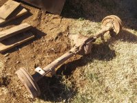
I did take a few pictures of the powertrain sitting on the pallet.


Again I wish I'd have taken some with the valve cover off, maybe some day, there are other pictures available online though. That last picture you can sort of see how unusual the bell housing side of things is. Only two bell housing bolts are visible with there being 5 total that connect the bell housing and block, the other three being hidden.

There is looking down the side of the engine block at the bell housing where you can see there isn't a wide flange on the back of the block like you will generally find on the transmission side of basically every other engine.

This picture is the back of a Jeep 258 cubic inch inline six for comparison. That's what everyone generally thinks of as a Jeep inline six with the 4.0 liter engine being essentially the same, but you can clearly see the wide boss sticking out from the block.
Now for a bonus at the end of this pointless tech heavy post, try and figure out what this thing here actually is.


So on to the fun stuff. If you've never used or heard about it, in my experience the Desktop Dyno program is actually a pretty accurate estimator of engines if you can use reliable information on it. I've tried to model several engines that we've had put on an actual engine dyno for the shop in the program and generally it comes out pretty close. Just this past week we got the 389 stroker Pontiac engine we built run on the dyno and it came in the engine made more power in reality than it did on the computer, 492HP to 480HP. Now the reason I bring this up is that I've been trying to figure the Tornado engine out on that program to get a real estimate of what it would do with a blower on it. Someone had done a couple sets of head flow numbers which is half the battle, the bore and stroke and induction and stuff is all pretty easily found online, but I never found any specs on the camshaft used.
I finally decided that since I was going in to work to do some maintenance on my wife and I's vehicles today that I would degree the cam and get some answers finally.
The interesting things here are that the lifts at the valves are different despite being the same cam lobe actuating both intake and exhaust valves. The lifts at the valve are different as well. I checked each point multiple times and measured to .050". There is a margin of error involved in the numbers because I can't be certain that my dial indicator was exactly parallel to the valve, plus I didn't use a degree wheel doing this. It's all based upon timing marks on the balancer. There are 30 degrees marked out on the balancer around TDC and I measured that every 10 degrees of rotation of the crank was 9/16 of an inch, marked the valve events and then string measured based upon those numbers. It's not super precise but I was expecting everything to be a little closer than this. I'm thinking it's an issue with where the rocker arm pivots are in relation to the cam lobe combined with the rocker arms not actually being an equal ratio.
Something else unusual here, and I didn't think to take pictures with the valve cover off, despite being an overhead camshaft engine the valve adjustment is by rocker height adjustment on the ball studs a la Chevy V8. There is a plate that mounts to the same studs that the rocker cover itself bolts to that basically has fingers that fit into the concave cavity of the stamped steel rocker arms to keep them from simply spinning around. Super goofy stuff, you would expect shaft mounted rockers like the XS cylinder head with the same type adjustment or at least I would. That is obviously a possible cause of the variation as well seeing as those fingers aren't well fit at this point, some of them have been repaired in the past even.
Having my numbers I put them into the Desktop Dyno program and what it returned was within 5hp and 5lb ft of what Kaiser had rated the engine at back in the 1960s. They rated it 140hp and 210lb-ft, the computer said 144hp and 214lb-ft. That gave me enough confidence to plug in the specs of the M90 supercharger we had been talking about and playing with drive ratios and what not because it will calculate intake manifold pressure as well to give me boost pressure as well. So the best guess I've got is driving the M90 twice crank RPM gives us a little over 5 pounds of boost at 5000rpm and numbers of 247hp 311lb-ft with the peak horsepower coming just over the 5000rpm rev limit the engine supposedly has.
I did take a few pictures of the powertrain sitting on the pallet.
Again I wish I'd have taken some with the valve cover off, maybe some day, there are other pictures available online though. That last picture you can sort of see how unusual the bell housing side of things is. Only two bell housing bolts are visible with there being 5 total that connect the bell housing and block, the other three being hidden.
There is looking down the side of the engine block at the bell housing where you can see there isn't a wide flange on the back of the block like you will generally find on the transmission side of basically every other engine.
This picture is the back of a Jeep 258 cubic inch inline six for comparison. That's what everyone generally thinks of as a Jeep inline six with the 4.0 liter engine being essentially the same, but you can clearly see the wide boss sticking out from the block.
Now for a bonus at the end of this pointless tech heavy post, try and figure out what this thing here actually is.
Great news from today, the Gladiator's owner came by the shop. The short version is he told me "Merry Christmas it's yours" with regard to the engine, so I now have a crazy old Jeep driveline. In an interesting moment I was talking about the desire to use a supercharger like the one that came on the old Thunderbird Super Coupe and he said that he had actually traded a 95 Thunderbird to get the Gladiator. So that was a neat moment of connection.
I have given more thought to the cam timing question and believe I have an answer. The rocker arms act directly on the camshaft and have a sort of wear pad made on to the arm that is shaped much like a rectangular box. My thinking is that box has to be worn on the edges to make it more wedge shaped than rectangle shaped which would delay the valve action without affecting the overall valve lift. Of course what that means is that the engine most likely needs a set of rocker arms, so I'll have to find those somewhere.
Things I did get, tires from Coker on closeout. Nowhere near time to get tires at the point obviously, but with the size and type I want being changed over to a new version the old version is cheap and going away so I wanted to pick those up. The other thing I got was front hubs ordered. We have still got a junk CJ7 sitting at the shop and I was thinking of taking the AMC 20 rear axle from it, but we now also have a junk Wagoneer sitting at the shop with an offset Dana 44 under it. We're thinking they are roughly the same track width and if that is indeed the case I'll grab the Dana rear instead. Getting front hubs that match the bolt pattern but are bolt in lead me to a 2000-2008 Grand Cherokee. That should be enough I can start designing the chassis, I've got a rough idea of what seems right but I'll start actually drafting stuff soon.
More fun stuff is that a coworker thinks he has a line on a supercharger for cheap. So that's another thing that I don't need to buy at the moment, but he's thinking it's probable getting it for about half what they go for on Ebay so it's a no brainer to get it now if possible.
REALLY looking forward to this build thread!
Boom!
I cleaned the valve cover tonight. Long for the days where they took pride and wanted to make things look good even on something like the valve cover of a bargain basement truck engine. Think I may eventually drop some black enamel on the Jeep Tornado 230 writing and leave everything else as cast, but not sure just yet. I did remember the pictures with the valve cover off tonight though.


Pictures there, can see the rocker arms/followers being ball stud mounted, which still seems like a limitation. The fingers can be seen here too. I didn't try to get a close up of it but there is noticeable wear on several of the fingers which will allow the followers to turn sideways on the cam lobes. You can see the wear tip on the follower in that third picture too.

Cook thing here if you can see it, which I don't know that you can. It looks like at some point in time the engine has been converted to positive valve seals which leads me to believe it's had a valve job done at some point which is nice. Money to rebuild the engine unfortunately just isn't on the table so I need it to be as nice as possible. The truck it came out of ran perfectly fine, no bad noises or crazy smoking or anything so at least until I put boost to it things work.
My wife is still hung up on the fact that we have no place to put a completed race car, but she just can't see the awesomeness of that only being a problem because we will have a race car. And a parting picture of the clean valve cover on the engine.

Venting time for a minute. I'm trying to look up information on the rear differentials I have available for free to me. I know the CJ7 is an AMC 20 and it has a 2.73 ring and pinion in it. The Wagoneer has an I have no freaking clue right now. I had assumed it was an offset housing Dana 44 because the Wagoneer is basically the SUV version of the Gladiator and the Gladiator looks like it has an offset housing Dana 44. The numerically low ratio of the AMC is nice because I'm all but stuck with a 1:1 high gear and 26 inch tires, so I'm looking for numerically low gear sets for a Dana 44, I can find down to a 3.07. That works the chances of the car ever being driven fast enough to bother, even though it's nice to think about that being an issue down the road.
Where things get fun is that when you go to the different sites looking for gear sets and they ask for make and model, a Dana 44 doesn't come up as a choice for the 1965 Wagoneer rear axle. One has it as actually being a Dana 60 which is super overkill and needlessly robbing power, others show it to be a Dana 53 which I hadn't ever heard of and you can't really buy parts for. The one thing the different places agree on is that the axle ratio in the Wagoneer is over 4:1 which I'm pretending simply won't work for me. The CJ axle on the other hand I'm told has notoriously weak 2 piece axle shafts that must be changed for any kind of hard driving purposes.
Have I mentioned that I tend to obsess over things? So I'm sitting here thinking I need to drive back to work and crawl under this junk Wagoneer to find out exactly what's under the back end of it. Didn't people keep track of things like this back in the 60s, maybe it was just a Kaiser Willys way of doing things.
First, RH finger; is that a brazed on replacement "fix"?

If it is I'd take that as a warning.
There are a few like that, those are a wear item of sorts on the engine being as they are the only thing that holds the followers straight on the cam. They do appear to be intentionally softer metal than that of the followers themselves so it there doesn't seem to be any big grooves or anything in the followers. There is at least one original finger that has a large amount of wear to it allowing a good bit of rotation of the follower. I was able to find a very reasonably priced set of new old stock followers so I'm happy about that as I still feel that's the reason the cam timing is funny. I can't however find anyone with a follower alignment plate.
I haven't mentioned the fix for this yet because I haven't decided how it's going to be fixed. The obvious way is to take the alignment plate off and weld new fingers on it, but that's just sort of just cobbling together the same flawed system it had originally. One thing going for that way is that if this thing sees another 1,000 miles in it's lifetime I'd be astonished. I don't see any scaring on the cam lobes themselves. Fun fact the camshaft itself is hollow and part of the oil passage system. Oil comes up into the cam through the cam towers and travels inside the cam to weep holes cut on the base circle of the cam lobes opposite the nose. It would be nice to devise some sort of more positive alignment system and I can think of ways to do that, just not cheap ways to do it.
In any event, rain tomorrow and both my potential rear axle donor vehicles are outside, so gonna head over after lunch and pick on and yank it. Gonna take my older boy with me and try once again to drum up some interest in working on and creating mechanical stuff.
Vintage racing tires showed up


To borrow a quote
"Back when the drivers were fat and the tires skinny"
To borrow a quote
"Back when the drivers were fat and the tires skinny"
Last edited:
More free junk and the even junkier junk that junk came out of. Dana 44 offset center section. 53 inches from backing plate to backing plate and a 3.31:1 ring and pinion. The axle spins without any trouble but I haven't taken the cover off or anything yet. At some point I'll take the cover off and see just how lovely everything is in there, clean the outside of it, and pull the parking brake mechanism and automatic adjusters out. No reason to have them on a race car so they're taking a hike. The spring perches and shock mounts will need to be removed as well. My thinking right now is to do a semi-triangulated three link with a Watts linkage to locate the axle and coil over shocks suspending the rear. I've played around with other ideas but I think for aesthetic and packaging that set up works best.
The 3.31 works and is numerically lower than I was expecting. It takes effective top speed to 110mph with a max in first of 40mph with second about 75mph.oing things
The possibility exists of doing rod actuated shocks inline with the frame rails just because we can. I haven't spent any time looking at shocks yet, but doing them off a pivot lets me play around with wheel travel to shock travel. There isn't any reason to have a ton of wheel travel in the thing, even 3 inches is probably way more than it realistically needs to be a race car. With the shocks as a direct linkage there is an excellent chance it would have at least twice that and probably more. Playing with the pivot ratio I can make the shock travel twice as far as the wheel for instance, which could in theory let the function of the shock be more precise over small movements. It will change the necessary spring rate too but the spring rate needed will be very light with very little weight on the rear axle especially.
Attachments

Continuing the barrage of the day, the first scale drawing I've done. Proof the idea, get a measurement going forward for what the wheelbase needs to be and the overall length of the thing should end up. Also tried to measure my body sitting and place my imaginary self in the vehicle to get an idea of seating position and such. It's all preliminary at this point obviously. I'm pretty sure I can lower the nose a bit as I drew this out conservatively in that I went off numbers that were taken roughly a couple days ago. Also I can't remember where I measured the length of the engine to, if it was to the nose of the water pump or just the block and timing cover.

Looking at it here I need to lower the rear deck probably six inches (two squares if you can't see the scale in the corner). The other thing about the front is that is without changing the oil pan any and I still believe I can cut a couple inches there which would enable more incline to the front bodywork that I desire. It once again makes me wish for taller tires but whatcha gonna do? Also the roll hoop may stay or go. The look disagrees with me but there is an undeniable need for it functionally.
Looking at it here I need to lower the rear deck probably six inches (two squares if you can't see the scale in the corner). The other thing about the front is that is without changing the oil pan any and I still believe I can cut a couple inches there which would enable more incline to the front bodywork that I desire. It once again makes me wish for taller tires but whatcha gonna do? Also the roll hoop may stay or go. The look disagrees with me but there is an undeniable need for it functionally.
Scripto VU
Dukes Speed and Custom
https://www.conceptcarz.com/profile/12033,19619/2007-murray-brothers-special-indy-roadster.aspx
https://www.throttlextreme.com/murray-brothers-garage-ultimate-custom-coupe-one-hell-hot-rod-build/
I tried to find the original articles in Hotrod magazine. ? (worth finding)
This is a local builder that knows how to build !!!!! (Thought you might get a charge out of it....maybe some ideas) Hot Rod of the Year 2008 . Both cars are
street driven and really fast. Amazing in person !
Murray Brothers is cool stuff, never heard of them. Depressing lack of easily available information on the cars. Seems just the same couple of broad images with either car. I'd love to see detailed shots with the bodies off, the coupe has a real nice look to it overall. I'm guessing they're pretty much identical underneath, can see the locators for a solid front axle on the coupe but that's really about it. It's weird you would expect the stuff to be searchable from Hot Rod magazine but nothing is coming up for me.
My hubs are saying they'll will be delivered today but I rather doubt it. At some point I may go and get better measurements and mess with the rear axle a bit, but don't have anything strictly planned out there. I kept drawing last night, altered the profile drawing behind the driver and like the result much better. I also did a first roughing in of a top down drawing of the frame. Once again I don't have good measurements and certainly don't have them here at the house with me. I do remember the other night getting 42 inches wide mentioned, it was measured rather unscientifically though....and it was measured while several of us were drinking beer and BSing.


The top down has the engine offset 3 inches to the right side of the chassis, at least looking at numbers vaguely that should help to even out the side to side weight balance. Having the engine 3 inches right roughly offsets the weight of my backside 10 1/2 inches to the left. I had been thinking of having the blower under the exhaust side of the engine on the right, but thinking further on it leads me to having it on the left. My plan currently is to have the battery and it's weight sitting right beside the driver atop the driveshaft tunnel and that throws the weight balance back off the right without anything to counteract it. Also looking at the drawing there is obviously more room for the blower to the left of the engine than the right and it simplifies plumbing and blah blah blah. Interestingly, according to the stuff I've run there will be no reason to have an intercooler on the setup. The M90 simply won't make enough boost to warrant the weight, complexity and pressure drop caused by an intercooler and it's plumbing.
Rambling from here to the end:
Honestly, I dislike the overhead and I hope it's largely wrong. The outside of the body is too close to the inside of the wheels and the front end doesn't pinch down enough. I do think it's probably wrong too, sitting here typing this it seems like the 42 inches was based upon the assumption that the engine was in the middle how much room my ass and feet needed to coexist beside it was 21 inches from center line. With the engine offset three inches that would shrink to 18 inches from center line. The engine itself is widest on the right side with the distributor cap and if remembering correctly it was 21 inches from the cap being the furthest point right to the outside of the alternator being the furthest point left. The waist should be able to go to 36 based upon that. That doesn't help the front obviously.
My hubs are saying they'll will be delivered today but I rather doubt it. At some point I may go and get better measurements and mess with the rear axle a bit, but don't have anything strictly planned out there. I kept drawing last night, altered the profile drawing behind the driver and like the result much better. I also did a first roughing in of a top down drawing of the frame. Once again I don't have good measurements and certainly don't have them here at the house with me. I do remember the other night getting 42 inches wide mentioned, it was measured rather unscientifically though....and it was measured while several of us were drinking beer and BSing.
The top down has the engine offset 3 inches to the right side of the chassis, at least looking at numbers vaguely that should help to even out the side to side weight balance. Having the engine 3 inches right roughly offsets the weight of my backside 10 1/2 inches to the left. I had been thinking of having the blower under the exhaust side of the engine on the right, but thinking further on it leads me to having it on the left. My plan currently is to have the battery and it's weight sitting right beside the driver atop the driveshaft tunnel and that throws the weight balance back off the right without anything to counteract it. Also looking at the drawing there is obviously more room for the blower to the left of the engine than the right and it simplifies plumbing and blah blah blah. Interestingly, according to the stuff I've run there will be no reason to have an intercooler on the setup. The M90 simply won't make enough boost to warrant the weight, complexity and pressure drop caused by an intercooler and it's plumbing.
Rambling from here to the end:
Honestly, I dislike the overhead and I hope it's largely wrong. The outside of the body is too close to the inside of the wheels and the front end doesn't pinch down enough. I do think it's probably wrong too, sitting here typing this it seems like the 42 inches was based upon the assumption that the engine was in the middle how much room my ass and feet needed to coexist beside it was 21 inches from center line. With the engine offset three inches that would shrink to 18 inches from center line. The engine itself is widest on the right side with the distributor cap and if remembering correctly it was 21 inches from the cap being the furthest point right to the outside of the alternator being the furthest point left. The waist should be able to go to 36 based upon that. That doesn't help the front obviously.
Got the hubs in today, and I gotta say I'm disappointed in the information source I was looking at before ordering them. Turns out they are actually 5x5 bolt pattern, not 5x5.5. It's not a huge problem, they are at least 1/2-20 studs so there will only be one lug nut size needed and the wheels I'm planning on using are dual pattern so they'll still fit all four corners. I hate being wrong because what I was using to help make my decision was wrong though. If you've seen one hub you've seen them all, but if you haven't here they are.


I went in this afternoon and got most of the measurements I wanted. I ended up taking the brakes off the rear axle by force to get the numbers from it. The Wagoneer only had one wheel on it and it was on the driver's rear, so it had dug the other side into the mud over the years and the brake shoes were rusted stuck to the drum, the adjusters on both sides were rusted solid too. I was expecting the brakes on it to be junk so no harm no foul so far. Weirdly though, both balancing bars were missing though so I'm not sure what's up with that. Driving home I got to about a half mile from my house and realized that I had neglected to measure the height of the crankshaft and transfer case output but odds are I'm close enough based upon the center of the bell housing. If I can remember come tomorrow evening I'll measure those to be sure.


So I've got Profile Picture version 1.2 now. My thinking this morning was correct with things related to the engine and transmission. So I was able to lower the nose over the engine a couple inches by taking two inches off the bottom of the oil pan which leaves 4 inches ground clearance. The funny thing with that image though is that I managed to wild ass guess the lengths and depths of the bell housing, transmission, transfer case and rear axle despite not actually having measured them before. I'm far happier with the taper of the front end now.
I can actually move the engine back, or shrink the wheel base some if I want to, but I'm not sure I want to. My six foot tall self will have room to spare with the dimensions drawn this way, but it certainly looks like my boys are going to be a bit taller when full grown. My boss is a couple inches taller than I am too and given his contributions it'd be nice to have him fit in it too. He and I were talking yesterday and he brought up the possibility of the car driving on the autocross course at the GoodGuys event here in Nashville when it's done and I told him he ought to do the driving.
The top down drawing I redid entirely. As I said above my thinking from this morning was correct so the original top down was all wrong. Wrong to the point that I realized this evening the top down has a different wheelbase than the profile. Oops? The drawing from tonight looks far more elegant to me, and it resembles what I have in my mind for this where the one before just looks bloated and cumbersome by comparison. I even added more detail to the top of the engine for this one. No front control arms on this one. Now that I have measured the hubs I can be more accurate than the thrown on arms of the first drawing but don't have the time for the tonight. Showing things to the wife this evening she mentioned liking the flat front in the new picture more than the pointed version of the previous drawing, so I drew a quick sketch of the grill design out too.

After drawing that out I realized it's apparently a fairly common play on the '33 Ford grill. I'm not going to say I wasn't influenced by them since there is an excellent chance I'd seen it done before, but I wasn't specifically thinking of that when I first started thinking of the design. This afternoon before heading in to the shop I was kicking around ideas for coloring too. I wanted to incorporate the basic idea of the international racing colors for the United States of the time being white with blue stripes. The typical twin longitudinal racing stripes for that don't work for me on this type of body however so I was trying to find some other way of working the colors. What I like right now is having the bulk of the body being an off white color and the grill surround back to the hood line being blue, and then having the business logo of the gentleman who donated the drive line slightly altered and done in a round logo based that same blue located on the body inside the rear tires. The wheels are going to be solid steel wheels with polished rims with the face a burgundy color and the seat done in matching cloth with vertical pleats. I don't know if the description sounds appealing but it works on paper. If you saw my thread about making my XS650 seat and painting that bike you know it's likely my color taste will change between now and time to paint this thing.
I went in this afternoon and got most of the measurements I wanted. I ended up taking the brakes off the rear axle by force to get the numbers from it. The Wagoneer only had one wheel on it and it was on the driver's rear, so it had dug the other side into the mud over the years and the brake shoes were rusted stuck to the drum, the adjusters on both sides were rusted solid too. I was expecting the brakes on it to be junk so no harm no foul so far. Weirdly though, both balancing bars were missing though so I'm not sure what's up with that. Driving home I got to about a half mile from my house and realized that I had neglected to measure the height of the crankshaft and transfer case output but odds are I'm close enough based upon the center of the bell housing. If I can remember come tomorrow evening I'll measure those to be sure.
So I've got Profile Picture version 1.2 now. My thinking this morning was correct with things related to the engine and transmission. So I was able to lower the nose over the engine a couple inches by taking two inches off the bottom of the oil pan which leaves 4 inches ground clearance. The funny thing with that image though is that I managed to wild ass guess the lengths and depths of the bell housing, transmission, transfer case and rear axle despite not actually having measured them before. I'm far happier with the taper of the front end now.
I can actually move the engine back, or shrink the wheel base some if I want to, but I'm not sure I want to. My six foot tall self will have room to spare with the dimensions drawn this way, but it certainly looks like my boys are going to be a bit taller when full grown. My boss is a couple inches taller than I am too and given his contributions it'd be nice to have him fit in it too. He and I were talking yesterday and he brought up the possibility of the car driving on the autocross course at the GoodGuys event here in Nashville when it's done and I told him he ought to do the driving.
The top down drawing I redid entirely. As I said above my thinking from this morning was correct so the original top down was all wrong. Wrong to the point that I realized this evening the top down has a different wheelbase than the profile. Oops? The drawing from tonight looks far more elegant to me, and it resembles what I have in my mind for this where the one before just looks bloated and cumbersome by comparison. I even added more detail to the top of the engine for this one. No front control arms on this one. Now that I have measured the hubs I can be more accurate than the thrown on arms of the first drawing but don't have the time for the tonight. Showing things to the wife this evening she mentioned liking the flat front in the new picture more than the pointed version of the previous drawing, so I drew a quick sketch of the grill design out too.
After drawing that out I realized it's apparently a fairly common play on the '33 Ford grill. I'm not going to say I wasn't influenced by them since there is an excellent chance I'd seen it done before, but I wasn't specifically thinking of that when I first started thinking of the design. This afternoon before heading in to the shop I was kicking around ideas for coloring too. I wanted to incorporate the basic idea of the international racing colors for the United States of the time being white with blue stripes. The typical twin longitudinal racing stripes for that don't work for me on this type of body however so I was trying to find some other way of working the colors. What I like right now is having the bulk of the body being an off white color and the grill surround back to the hood line being blue, and then having the business logo of the gentleman who donated the drive line slightly altered and done in a round logo based that same blue located on the body inside the rear tires. The wheels are going to be solid steel wheels with polished rims with the face a burgundy color and the seat done in matching cloth with vertical pleats. I don't know if the description sounds appealing but it works on paper. If you saw my thread about making my XS650 seat and painting that bike you know it's likely my color taste will change between now and time to paint this thing.

Well, I think I painted myself into a weird corner. I was thinking about control arms today and happened to think that I need to know the back spacing of the brake rotors I'm using in order to know where the spindle and in turn ball joints can be in relation to the wheel mounting surface. Moving with that line of thinking I started looking for brake bits for my front axle, and I've run into a problem. I got Grand Cherokee hubs because they bolt in and use 1/2 inch studs, and was led to believe they had a 5x5.5 bolt pattern which they don't..They have a 5x5 bolt pattern, and where things start getting wonky is that the Grand Cherokee's smallest available wheel at the time was 16 inches. 16 inches of course is an inch more than the 15 inch tires I've already received so the brake parts for the Grand Cherokee will almost certainly not fit in my wheels.
The big problems start coming in about the time you look at the list of vehicles that used 5x5 bolt pattern wheels. It's all trucks and old rear wheel drive stuff. All the stuff that's rear wheel drive the brake rotors had integrated hubs, so the rotors won't work with the hubs I have. All the 4 wheel drive stuff has separate hubs and rotors but the brake caliper brackets are integrated into the knuckles. Now I could make a pair of caliper brackets but I'd rather not. Especially not when you can just buy caliper brackets for the integrated hub rotors for so cheap, they're mocking me.......
What I'm looking at right now I think is getting Grand Cherokee rotors and Chevy Caprice calipers and brackets. The Caprice and Grand Cherokee rotors are listed as the same thickness, and thanks to the 96 Impala SS you can get decent pad compounds for those calipers. Unfortunately the Grand Cherokee rotor is .140" larger in diameter. Working simply on theory at this point leaves me with no real idea as to whether that .070" radius is enough to be problematic. There also aren't measurements given for hat diameter of the two vehicles so there is a chance the caliper bracket from the Caprice will interfere with the rotor hat of the Grand Cherokee even if you machine that .070" from the rotors. The inside of the steel wheels are a complete unknown at this point too. Where the wheel face is welded to the wheel rim could present a problem too. Backup thinking is an old Chevy Astro 4wd van. They had the bolt pattern and 15" wheels with slip on brake rotors so all that Should work, but they also had the integrated caliper bracket so I'd have to make caliper brackets to use them. In any event it looks a lot like I need a wheel. Access to the caliper and rotor I can easily get from the local parts store and just send them back if it's insurmountable. Wasn't really looking to spend money on wheels right now but that's life.
Other happenings from today are that I got the measurements I forgot to grab yesterday and once again shocked myself with the accuracy of my guesses. I was like a half inch off on where I drew the output flange and the height of the bell housing and transmission case. I've wasted most of the evening trying to work out the brake dilemma and have only come to one knew conclusion on the day. When this is all said and done I need to put one of those "It's a Jeep Thing" stickers on the dash.
If it was easy, everyone would have a race car in their garage. 
If it was easy, everyone would have a race car in their garage.
HaHa yeah, who would've thought building an entire car from scratch around a couple obscure parts from the sixties would be tough right?

So anyway, ordered a wheel this morning. Coker said they were custom made so heaven knows when it'll get here. Took a peak at the expense involved in going up to 16 inch wheels and tires......don't wanna go that route. Machining the Grand Cherokee rotor should be easy enough if it comes to that, re-balancing it will take some rigging but it's not the end of the world.
Talked to the guy that does our glass stuff at work today and he said he'll let me have a piece of scrap new glass next time he's by. I can hold on to it until I'm ready and then once I've got a pattern he'll cut it for me. So eventually I'll get a free little piece of glass made for the tiny windshield I'm going to do on the car. Looked at gauges last night and like the Vintage line from Class Instruments best from what I've seen. Even that stuff is unpleasantly expensive.
I know I could do things cheaper as I've got access to free left over stuff through work, but I I'd rather not go that route. Not that I want to go the expensive route either. Feels like I've only just begun and the project is teetering over the edge of cheap fun thing to occupy time into serious project territory. At this rate I may end up spending enough that I feel like I've got to start regularly auto crossing the thing or something, as if that isn't a great example of sunk money fallacy.
In other news, it's been brought to my attention that what I thought was interesting commentary and discussion about this process is in fact "boring technical crap". It wasn't from anyone on here, but it did get me thinking I've spent a good bit of time typing all this stuff out and people may just be more interested in the pictures and small captions approach. Not that I plan on changing anything, it's easy to ignore the words and skim if that's what anyone desires. I'm doing things the way I would like to see them done if the situation was reversed.
Similar threads
- Replies
- 22
- Views
- 3K