1971 carbs throttle shaft caps staked on. How to remove?

gggGary

If not now, When?
Top Contributor
XS650.com Supporter
Messages
30,951
Reaction score
60,904
Points
813
Location
Baraboo, WI, USA
Started overhauling a set of XS1B carbs. The throttle shafts have staked on sheet metal, cap one side and cover with the shaft poking though on the other.
Anyone got the hot tip for removing these? Hopefully so they can be reused... Do they have the seals like the later years or is something different hiding under there?

xs1b carbs.jpg

Left carb has 10 minutes (so far, no brushing) in the harbor freight cheapie ultrasonic cleaner with generic pine cleaner and water.

tags;
XS1 XS1B XS2 carburetor carburators BS38 overhaul repair butterfly how to JIS2 JIS #2
 
Wow, been a million years since I opened my other carbs. Haven't cracked into the current set yet. Something in the back of my head tells me my thoughts back then were: 'If I had just twist/rotated that cap, the retension nubs would've just climbed out of their notches.'
 
Like 2many suggested lubed them, grabbed with a pair of slip joint pliers, gentle twist and lift. Took a bit but they came off in good shape. One seal underneath was OK the other was toast. I will polish the shaft and replace both seals.

xs1b carbs 007.JPG

Seals; Yamaha Part # 256-14997-00 used on hundreds of models readily available everywhere about 3.50 each 4 needed.
 
This is a project I'm planning for my worn XS1B BS38 carbs in futurespace:

If you believe that you may have worn throttle shaft bores in the throttle body:

The scenario goes kinda like this:

When new, the steel plated brass throttle shaft fits closely in the aluminum Zamak throttle shaft bore in the aluminum Zamak throttle body. The throttle valve disc is precisely fitted into the throttle shaft slot so as to completely close-off the throttle opening when fully (minus stop screw) closed. The throttle disc edges are slightly angle-bevelled so that the throttle disc fits snugly to the bore walls. Also, when in this fully-closed position, the transfer slots/ports are covered, not exposed to engine-side vacuum. The idle port is the only exposed port in this position.

This is the proper restore configuration after full carb disassembly, or after replacing throttle valve seals.

Here's where the problem comes in. The BS38 throttle valve area is about 2 square inches. It must resist the pressure difference between ambient atmospheric (14.7 psi) and manifold vacuum (as low as 1 - 1/2 psi). This means that as much as 10 - 25 lbs of force is trying to press the throttle shaft towards the engine port. Also, manipulating the throttle with the throttle cable induces rubbing wear and a load in the direction of the pulling cable (in this case, up). Combine those two forces and the longtime wear, you'll end-up with a throttle shaft bore that's wallowed up and to the left (10 o'clock, as viewed straight on at the throttle arm from the left side of the bike). You can confirm this by wiggling the throttle arm/shaft (engine off) up/down and left/right. Anything more than a couple thousandts shows a worn throttle shaft bore.

If the carb is properly reassembled, and the idle stop screw set a fraction of a turn off fully stopped, the bike should start and idle fine, until the throttle is 'blipped' while the engine is running. Then the combination of vacuum and cable force will pull the throttle shaft off-center (up and to the left), and the throttle valve disc will now prematurely contact the bore, or get very close to it, causing mechanical sticking and transfer slot/port starvation, AND admitting excess air at the opposite edge of the disc, creating a lean condition, and a high idle.

Good hi-dollar carbs are fitted with replaceable bushings (like Holley), but most are not. I've been able to successfully line-bore and bush worn throttle bodies, but the setup time takes forever. It's worth it though, if if you're trying to restore a $2000 Marvel-Schwebler!

I've noticed several posts here where some folks have restored functionality by replacing throttle shaft seals, but that is short-term.

An effective band-aid can be done by recentering the throttle valve disc with the throttle shaft displaced toward the worn zone. Tricky, can be done, that's the way my wore-out BS38's are setup now. Also, setting the idle ignition timing at its most retarded position helps, as this forces you to nudge the idle stop a little higher, avoiding the disc/bore interference and eccentricity near full close. Of course, the idle mix screws have to be set to accomodate this situation.

My carbs will eventually need to be line-bored and bushed. Refitting throttle shaft seals is not the same thing.

I've thought about making a rebore/bush jig for BS38's, but found this method utilizing a modified reamer, and using the reamer shaft as the guide:
 

Attachments

  • ThrottleReaming01.jpg
    ThrottleReaming01.jpg
    265.5 KB · Views: 334
  • ThrottleReaming02.jpg
    ThrottleReaming02.jpg
    192.1 KB · Views: 353
  • ThrottleReaming03.jpg
    ThrottleReaming03.jpg
    113.4 KB · Views: 335
Last edited:
Yes worn housings is a real concern. This bike is not real high miles about 12-15K IIRC, the capped side is tight yet, the arm side is not tight but to my fingers still acceptable. That is one good thing about the midwest we do not have the constant fine dust the southwest has so we don't get as much wear. I got a set of southwest carbs one time and like you say the throttle bores were completely shot, the bodies were useless. This is an often forgotten issue when guys are having problems. That's a nice write up, thanks for that. I think I will try to do a photo shoot of the overhaul, there are significant differences on the linkage between these and the later carbs.
 
2many you have me thinking. Could we plate the shaft bores and then ream them? Caswells sell swab plating kits. Is the carb body aluminum or die cast? My thought is to build up the bore with say brass plating, ream it using a centering bushing and a back cut reamer like above, refit shaft with new seals, done?
This would be my hope. These bodies will probably work as is but the wear can be felt on the cable arm side, they aren't ideal and I have at least three more sets of early carbs to do.
Looking through caswells maybe copper?

The parts count in these early carb chokes is through the roof. After a two week layoff reassembly is driving me nuts, good thing I had other (still assembled) sets to look at.
 
I'd have to do some digging in the barn to find a XS1/XS1B carbie, but in later units the throttle shaft runs in brass bushings, not on aluminum. With the bright idea of finding standard stock to use for replacement, I pulled one of the bushings awhile back--threaded it, ran in a screw, heated the carb body, and pulled. Sadly, the OD of the bushing was stepped, and the big end of it was splined. The bushings would have to be line bored for new liners and the liners would have to have a very snug fit. I can't picture anything as small as the liners would need to be surviving the installation. gggGary, I think you have a good idea.
 
2many you have me thinking.

Oh, dear, I'm terribly sorry ..................................... April Fool's !!!

Could we plate the shaft bores and then ream them? Caswells sell swab plating kits.

Haha, I like the idea, but plating to aluminum Zamak is a touchy area.

Is the carb body aluminum or die cast?

Cast aluminum Zamak, unknown alloy. Those were the early transition years when Japanese manufacturing and metalurgy were improving from post-war recovery. Possibly melted-down soda cans.?.?...

My thought is to build up the bore with say brass plating, ream it using a centering bushing and a back cut reamer like above, refit shaft with new seals, done?

There's one good bearing surface in there that would be a good guide for the oversize reamer shank, the unworn bottom/rearward surface. The idea would be to do the oversize ream while gently pressing the reamer shaft against this reference surface, so the oversize hole would remain concentric to the original bore. If the bore were plated, that surface is gone, and a jig would probably be needed to guide the reamer.

It would be wonderful if you could simply put a drop of some self-wicking babbet-type wear-tolerant bearing restorer in there. Something that would bond to the aluminum Zamak, but not to the shaft (or slightly oversized reference pin). But that doesn't exist yet?

My cigarette making machine has a rectangular piston with a tough teflon coating on one side. Wonder how they did that...

This would be my hope. These bodies will probably work as is but the wear can be felt on the cable arm side, they aren't ideal and I have at least three more sets of early carbs to do.

Yeah, my mind drifts back to the '70s technology, using things with which I'm familiar, like reamers and replacable bushings. Still trying to catch-up on modern chemistries, methodologies, industrial processes.

Only 3 sets? You know, it breaks my heart to think of how many otherwise good carb bodies have been tossed just because of worn throttle bores. It would be great to be able to save them from the trash heap.

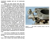
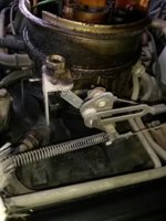
Pic #1 - Here's my country-bumkin shadetree fix for a worn throttle body in my '90 Blazer. The short spring in the middle of the pic holds the throttle shaft to the unworn side of the throttlebore, upwards and forward, pulling up and away from the throttle cable tension. The throttle shaft simply pivots in the spring's curved hook end. This is a throttle body injection system, looks like a carb, but doesn't have fuel orifices around the butterfly valves. So this bandaid doesn't affect idle mixture. It just keeps the butterfly plate from grabbing/sticking in the throttle bore.

Looking through caswells maybe copper?

I had friends in the polishing and chrome-plate industry back then. They did some jobs for me, including triple-plate chrome on aluminum, a disputable practice. Had to do the copper first since the nickle and chrome wouldn't bond reliably to the aluminum. But, the copper/aluminum bond is tedious as well, since long-term life is at risk of the bimetallic corrosion that occurs at the aluminum/copper interface.

But things have changed over the years, maybe there's new chemistries in that kit that would make this as simple as painting. Worth investigating and trying.

Just want to avoid any chance of debonding and risk a stuck throttle...

The parts count in these early carb chokes is through the roof. After a two week layoff reassembly is driving me nuts, good thing I had other (still assembled) sets to look at.

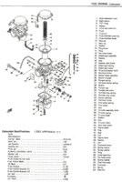
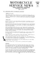
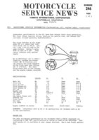
Pics #2, #3 - In case you don't have them, here's more to add to your collection, XS1 carb changes, MSN 246, pgs 1-2

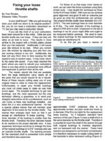
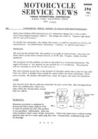
Pic #4 - More info on the E1 to E3 carb change, MSN 294
 

Attachments

  • SKMBT_C55211031017150_001815.jpg
    SKMBT_C55211031017150_001815.jpg
    110.8 KB · Views: 270
  • SKMBT_C55211030814490_00153.jpg
    SKMBT_C55211030814490_00153.jpg
    125.9 KB · Views: 278
  • SKMBT_C55211030814490_001402.jpg
    SKMBT_C55211030814490_001402.jpg
    92.4 KB · Views: 278
  • 90BlazerCarbSpring01.jpg
    90BlazerCarbSpring01.jpg
    61.9 KB · Views: 258
Last edited:
OK it looks like the the cable side of the shaft bore has a bushing the other side is plain. It's the side with the bushing that wears first.
If it isn't oilite bronze, the bushing might be easier to plate? It appears the outer seal lip has also been machined concentric to the shaft hole so that might make a reference for reaming?

xs1carbs 003.jpg

LH choke assembly order.

xs1bcarbs 003.jpg

And assembled
Choke installation order is important, assemble plunger and all parts into choke body.
Install start shaft into carb body
Install choke assembly with gasket to carb body, with start shaft shaft fingers in TOP slot in plunger. Then install choke lever assembly.

xs1bcarbs 008.jpg

The start shaft bracket/arm appears bent "crooked" but this is necessary to properly engage and freely move the plunger. Resist the temptation to "straighten" it.
 
I used to use long series 10mm drill bits that we had a tool maker grind down so the cutting end would guide in the other side. The grind was down to a couple of thou under 8mm and to a length of maybe 100mm. This left a nice square face which, once drilled to bush depth plus a few thou, would be perfect to press in a DU series Teflon lined bush exactly the same as the clutch pushrod bush MikesXS sells, part #01-2020 (he does not make them so you are safe).

We found there was no discernible (word?) difference whether it was done by hand, in a lathe or jiggled up on a mill. So we did it by hand.

If you had a similar drill ground for, say $20 I'm sure you could go into business, in the US anyhow.

Hope this helps.
 
Great stuff XSBob and 2many!
Would like to see pic of that drill bit if it still exists!
 
Sorry, not got a drill to show you gggGary but I have thought about getting another one made for the 8mm Xs spindles. We had ones to do carbs with spindles sizes of 1/4", 5/16", 7mm & 8mm which was the vast majority of the carbs we did and those split DU bushes are readily available in many sizes. If you get a few bushes (suggest from a bearing supplier) and ask them the correct size for an interference fit, then any toolmaker/grinder should be able to do the drill. It really was as simple as grinding down the flutes to a step.

Those brass bushes you can see in the castings are actually cast in (usually they are splined to keep them from moving) and are then bored from a datum point on the casting. If you pull one out it is almost impossible to get the hole in line and concentric again as the cast in part is rarely concentric to the later drilled and reamed hole.

The bush in gggGary's 1st picture is a split Teflon lined bush that has been retro fitted.

Oh, and don't polish your shaft too much cos you'll wear it out.

Hope that helps and makes sense.

Just did a search and this pic from the internet shows exactly what the drill was like
http://quadrajetparts.com/images/pr...quadrajet-throttle-shaft-bushing/Q4301-wl.jpg
 
Last edited:
Back
Top