GeorgeOC
XS650 Junkie
The little end cap simply unscrews from the top of the plug George...
Pete
Thank you Pete! Who knew! (Ha! I'm sure everyone but me..). Thanks for the help.
The little end cap simply unscrews from the top of the plug George...
Pete
Thank you Pete! Who knew! (Ha! I'm sure everyone but me..). Thanks for the help.
Door is wide open! Just be sure to pack the soldering iron along with the swim trunks...It is winter here and so I am always happy to help a guy who lives in a place with better weather than we have...who also has spare bedrooms!
Just kidding!!!!
Cheers,
Pete
You're on beach boy!!Door is wide open! Just be sure to pack the soldering iron along with the swim trunks...
Beach Boy... ha! Guilty as charged I suppose!You're on beach boy!!
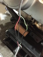
All seriousness aside - the soldering job looks good - have you tried to start it yet?

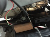
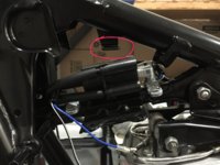
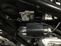
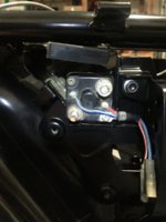
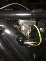
...My primary concern is the coil now will sit directly in the way of the flasher relay. Im going to pour into the site and look for a solution, but thought I'd throw this out for the community to see in case there is a slick fix.
Thank you Pete! Who knew! (Ha! I'm sure everyone but me..). Thanks for the help.
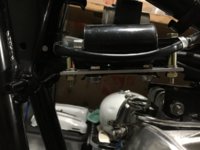
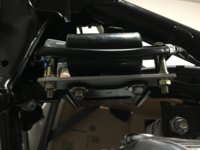
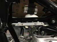
I don't think I'd use those ground clamps for the coil mounting. You have the two original coil mounting spots to work off of. I would make a light gauge angle bracket to bolt down to one of them. Rotate the coil so it's mounts face sideways and bolt it to the vertical leg of the new angle bracket with bolts through spacer tubes. You could offset it to one side and probably gain the space back for the flasher. I would also face the plug wires to the rear like the original coils had them.
I think I can hear this girl, but still off in the distance... First off, on the mounting of the new starter switch unit, I need to remove my head from ass, and get out the drill.OK - lets hear the thunder!