theDQG
XS650 Addict
Still going with the motogadget stuff? The M-unit and M-button? I'll be following closely if you do that. I'm going that route.
I am afraid I have abandoned that approach... I hate to say it, but I was way too overwhelmed with possible variables and compatibility issues. So, I've since sourced a complete stock electrical setup, and am in the process of installing as we speak. With the exception of a new PAMCO to replace the points. Post to follow on the install of the stock harness etc...Still going with the motogadget stuff? The M-unit and M-button? I'll be following closely if you do that. I'm going that route.
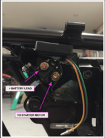
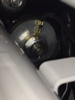
I've installed the new replacement starter relay... see here. And if I understand RG correctly, these would be the connection points for the terminals.George......................there is no polarity on those connections. You can connect the primary side of the contactor coil anyway you like. Same for the secondary side..................obviously the battery cable will connect easier to the top stud on the contactor.
Thank you Pete. Fancy paper weight eh!Hmmmmm....indeed. Is there a missing bracket or strut? In any event, THAT looks really nice GeorgeOC - very classy indeed.
Now - how is the wiring going and when will you push the little black button....
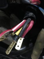
 ! I am stuck with the the connections to the solenoid and safety relay. There seems to be quite some controversy as to where the Red/white goes...
Absolutely Pete, thank you once again. Going back into the cave to follow some wires...!Sorry - but that's the best I can do right now. I hope uit helps a bit at least.
I thought we had this straightened out in the other thread. Any diagram that shows a red wire going to the Safety Relay is wrong.Thank you Pete. Fancy paper weight eh!
- Coming safety relay are the following: Red, Red/White, Black, Yellow.
- Off the starter solenoid: Red/White, Blue/White
I thought we had this straightened out in the other thread. Any diagram that shows a red wire going to the Safety Relay is wrong.
Look at the 1977 wiring diagram in the TECH section. It shows the correct wiring. For the Safety Relay, red/white comes in from the Stop Switch. Another red/white goes out to the starter solenoid. A blue/white leaves the starter solenoid going to the start push button. There is no red wire at the safety relay.
So where is the controversy?