VladTheDrumpaler
XS650 Enthusiast
Before I start, I'd like to thank everybody that has already helped me get this bike going. I'm learning each day and I feel like I understand the general flow of the system for these bikes. I am a 120/208 single/triple phase electrician by trade, but my knowledge of electrical systems for motorcycles is certainly lacking to say the least. It's been a long couple of weeks working on this bike and I forget basic protocol all the time. I normally write stuff down so I don't forget the broad strokes. It's been several years since I have gone pube deep in a bike so feel free to speak to me like I know nothing. I'll be as descriptive as I can and post plenty of pictures of everything that is currently on the bike.
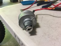
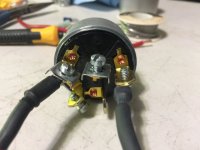
I've looked over this sticky, http://www.xs650.com/threads/9625, and educated myself on the stock electrical flow. My bike has been torn apart and the stock harness no longer exists. I have an XS Charge regulator and I need some assistance in verifying its proper install. It was installed by the PO and I feel like I need to double check the wiring. I've found quite a few anomalies across the rest of the bike so I don't really trust this build. The regulator doesn't really have any identifying marks or part numbers on it so I have no way of knowing what it is or if it is even correct.
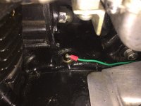
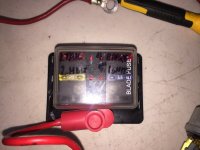
I have added a fork bag for the wiring of the switches, headlight, horn, turn signals, and relay. I added a grounding bus in the bag because of the massive amount of grounds for the front end. One side of the bus feeds directly from the negative on the battery and the other side grounds to the chassis near the coil. I ran a main power feed from the battery area, not hooked to the battery pos (+) though because that would kill the battery when the ignition switch is set to (on). I get the feeling that the installed charging system is not functioning correctly. Even if I were to connect the front end power feed directly to the pos (+) on the battery, It should still be maintaining the voltage. This is not the case. The battery died on my way to the tag office yesterday and I lost all peripheral devices.
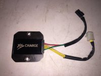
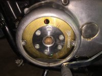
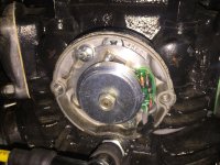
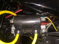
The regulator that I have is pictured below (XS Charge). Three yellow wires heading into the left side cover, assuming it goes to the charging system, and red going to the pos (+) terminal on the battery and green grounding on a chassis point of some kind. I guess the first thing is to identify the charging system for my own knowledge. Next would be to verify the correct routing and install of the wires. And finally, testing the system for proper charging and output voltage. Additionally, I installed a bigger battery yesterday. The previous battery was a TX12 180cca and it has been replaced with a TX14 200cca. I did this because, even after a full overnight charge, the TX12 was pretty sluggish in turning over the motor. The TX14, with a full charge, turns it immediately and the bike fires every time.
Side Note: I had some power delivery issues with the bike running very poorly. Swapped to new NGK BP7ES and it legitimately screams. I know that the sluggish firing of the motor was most likely due to bad plugs, but I swapped the battery anyway. I'm very impressed with the power of these bikes. Much more than I expected. Pleased and pleasantly surprised...
I know there are other threads about testing the charging system, I have been pouring through them, but since most of those other threads deal with the stock electrical system, I'm afraid that I need more clarification. I'll post additional pictures of the points and coils later on in this thread but I'd like to deal with the charging system first. Thanks in advance!!!!
I've looked over this sticky, http://www.xs650.com/threads/9625, and educated myself on the stock electrical flow. My bike has been torn apart and the stock harness no longer exists. I have an XS Charge regulator and I need some assistance in verifying its proper install. It was installed by the PO and I feel like I need to double check the wiring. I've found quite a few anomalies across the rest of the bike so I don't really trust this build. The regulator doesn't really have any identifying marks or part numbers on it so I have no way of knowing what it is or if it is even correct.
I have added a fork bag for the wiring of the switches, headlight, horn, turn signals, and relay. I added a grounding bus in the bag because of the massive amount of grounds for the front end. One side of the bus feeds directly from the negative on the battery and the other side grounds to the chassis near the coil. I ran a main power feed from the battery area, not hooked to the battery pos (+) though because that would kill the battery when the ignition switch is set to (on). I get the feeling that the installed charging system is not functioning correctly. Even if I were to connect the front end power feed directly to the pos (+) on the battery, It should still be maintaining the voltage. This is not the case. The battery died on my way to the tag office yesterday and I lost all peripheral devices.
The regulator that I have is pictured below (XS Charge). Three yellow wires heading into the left side cover, assuming it goes to the charging system, and red going to the pos (+) terminal on the battery and green grounding on a chassis point of some kind. I guess the first thing is to identify the charging system for my own knowledge. Next would be to verify the correct routing and install of the wires. And finally, testing the system for proper charging and output voltage. Additionally, I installed a bigger battery yesterday. The previous battery was a TX12 180cca and it has been replaced with a TX14 200cca. I did this because, even after a full overnight charge, the TX12 was pretty sluggish in turning over the motor. The TX14, with a full charge, turns it immediately and the bike fires every time.
Side Note: I had some power delivery issues with the bike running very poorly. Swapped to new NGK BP7ES and it legitimately screams. I know that the sluggish firing of the motor was most likely due to bad plugs, but I swapped the battery anyway. I'm very impressed with the power of these bikes. Much more than I expected. Pleased and pleasantly surprised...
I know there are other threads about testing the charging system, I have been pouring through them, but since most of those other threads deal with the stock electrical system, I'm afraid that I need more clarification. I'll post additional pictures of the points and coils later on in this thread but I'd like to deal with the charging system first. Thanks in advance!!!!