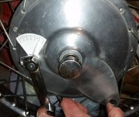
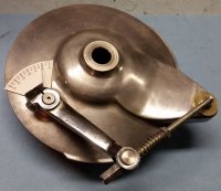
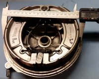
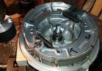
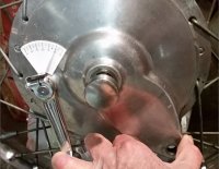
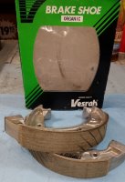
650 Rear Drum Brake Plates

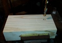
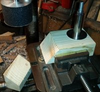
Clamp the block of wood in the vice of the XY table.
We want its top surface to be perpendicular to the drill press spindle. A top skim with end mill bit or flycutter could be done. My sanding drum has abrasive on its bottom, suitable for this squaring-off top skim.
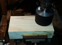
BrakeShoeArcing03.jpg

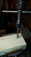
Change over to a 5/16" drill bit. Set the 3/8" fender washer atop the wood block as a drilling guide, ensuring that the washer has full coverage support by the wood.
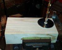
BrakeShoeArcing04.jpg

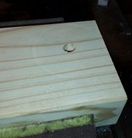
Drill the 5/16" hole.
BrakeShoeArcing05.jpg
 
Last edited:
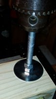
Next is to thread the 3/8" allthread stud into the wood.

These drill/tap/install operations are all done without disturbing the XY table. We want this allthread stud to be exactly perpendicular to the wood block, and parallel aligned with the drill spindle.

Lock (2) 3/8" nuts on the stud. Use the drill chuck as a guide to thread the stud into the wood. It'll start easily at first, then will tighten-up as it starts to cut it's own threads.
BrakeShoeArcing08.jpg

I ran it down about 1-3/8".
BrakeShoeArcing09.jpg

Unlock and remove the nuts.
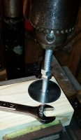
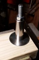
Place the larger 3/8" fender washer over the stud.
Place the wristpin over the stud.
Run a 3/8" nut down onto the wristpin and tighten.
Not so tight as to strip the wood threads.
BrakeShoeArcing10.jpg
 
Last edited:
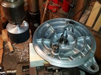
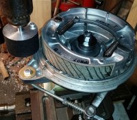
Now the drillpress head, or table can be swung to the side. The XY table can be moved over. Chuck up the sanding drum. You'll want about 5" between the side of the sanding drum and the center of the mounted wristpin.

Place the brake backing plate over the wristpin. Swing it around to check its clearances.
BrakeShoeArcing11.jpg
 
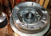
Assemble the brake backing plate, cam (index dot inboard), brake lever, and brake shoes.

My new shoes are bedding-in and showing the beginnings of full-arc contact. They'll be used to establish the initial settings of the drillpress and XY table.

As installed with no brake lever angle, they measure 179mm diameter, as specified by the brake shoe makers.
BrakeShoeArcing12.jpg

Place this assembly, with axle, into the 180mm brake drum.
Squeeze the brake lever to find the lever's angle when the shoes make full contact.
BrakeShoeArcing13.jpg

I'm showing about 11° of lever angle.
 
Now, attach the gadgetry for holding and indicating the brake lever. Dial-in the compression nut to the same angle, about 11°.
BrakeShoeArcing14.jpg

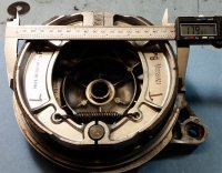
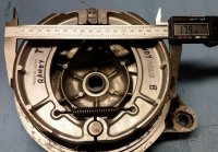
Measure the new shoe diameter.
BrakeShoeArcing15.jpg

Showing 180mm, good, matches the hub internal diameter.
 
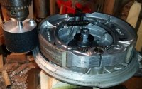
After the brake assembly is fitted over the wristpin, slide the axle spacer atop that, followed by a 3/8" fender washer and (2) 3/8" nuts.
BrakeShoeArcing18.jpg

The (2) 3/8" nuts are set and locked so that the backing plate is pressed-down, so it can't wobble/rock. Want some drag while rotating the backing plate, but not so much to make it difficult to turn.
 
We're just using this brake assembly to establish positions and origins.

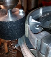
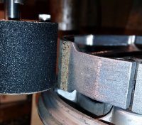
Lower the sanding drum to get full coverage on the brake shoes, but not so low as to catch the rim of the backing plate. Crank the XY table over until the sanding drum just begins to make contact with the brake shoes. Rotate the backing plate assembly, and make sure that the sanding drum is only touching at the high spots.
BrakeShoeArcing19.jpg

This is now the 180mm diameter position.
Zero-out the XY table's X and Y dials.
The origin is now established, and shoe grinding can commence.

But not on *these* shoes...
 
Crank back the table, remove the brake assembly, dial the lever angle back to zero, remove the shoes.

Let's mount up Machine's (Randy's) problematic oversized Vesrah shoes.
With the brake lever at 0°, their diameter is 0.26mm above normal.
BrakeShoeArcing21.jpg

Leaving the brake lever at 0°, mount it up to the fixture.
Crank the table in to where the cam side of the shoes just contact the sanding drum.
BrakeShoeArcing22.jpg

The table still has another 0.015" to go before reaching 0. Even with no preset on the brake lever, the shoes are oversized at this end.

Now spin the brake plate to the anchor post side of the shoes.
BrakeShoeArcing23.jpg

Quite a gap in there at this end.
It would seem that these shoes may have been arced at the correct 179mm diameter, but their arc centers are off, biased away from the anchor post.

Let's give it a go anyway.
Paint diagonal lines on the brake shoes, as indicators of material removal.
BrakeShoeArcing24.jpg
 
Change/increase the drillpress spindle speed for sanding.
Dial-in a 10° preset on the brake lever.
Crank in the table to where the shoes are close.
Rotate the brake assembly to a safe starting point, anchor post towards the sanding drum.
Turn on the drillpress (sander).

Slowly rotate the brake plate Clockwise (against sanding drum friction) one full turn.
Advance the table 0.005", or 0.1mm.
Slowly rotate the brake plate again, stop, advance the table, repeat.
Continue until reaching the 0 origin, which should give a 180mm diameter.
 
Last edited:
So, how did it go?

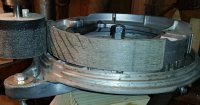
A lot of cutting on the cam side of the shoes, nothing on the anchor post side.

The Trailing (bottom) shoe. Cam to the right.
BrakeShoeArcing25.jpg

The Leading (top) shoe. Cam to the left.
BrakeShoeArcing26.jpg

Material was removed from only the cam-side half of the shoes.
Remove the brake assembly from the fixture, remove the brake lever gadgetry.

Fit the brake assembly, with axle, into the wheel hub.
Squeeze the brake lever to shoe contact.
BrakeShoeArcing29.jpg

Yup, 10° of lever travel until shoe contact.

These shoes will work. But they're defective, and will only have 1/2 of normal surface contact. The anchor post sides may not see use until the brakes are quite worn, or maybe not. Put them back into their box as emergency spares...
BrakeShoeArcing30.jpg


***** End of report *****
 
Super and detailed write up, how to in the usual 2M awesome manner!
Confession; while shuffling a bunch of parts to/from the shed/garage I have misplaced the plate with "garyized" new pads. o_O :redface: Will get some measurements, maybe mount up on lathe and scrub into a drum for a bit see how they start to seat, when I find them.
 
Thanx, gggGary.
This project and writeup kinda wore me out. Gettin' older.

Posts #84 - #89 are rather extraneous, unnecessary. Mostly a combination of examining my new shoes, and thinking this thing out.

They can be replaced with this simpler setup.

Make a spacing gauge block or bar, precisely 80mm (3.150") long.
Place between the wristpin and sanding drum.
BrakeShoeArcing31.jpg


Move the XY table so that the guage block just touches both.
This is the XY table's origin.
Zero-out the X and Y dials.
At this origin, the sander will cut the shoes to a 180mm diameter...
 
I just wanted to give a little update on my "corrected" brake cam install. I've had a chance to ride the bike several times now since I fixed the cam and I must say, I'm really liking the results. The brake is much stronger than it was before and works much better than it ever has. And it only seems to be getting better the more I use it. So, a big shout out and thank you to 2Many for discovering this obscure and little known important assembly detail .....

arKDkY2.jpg
 
Last edited:
I spent the better part of Saturday on my rear wheel. I changed the bearings, sprocket, sprocket bolts and lock tabs, tube and tire, and installed new Vesrah brake shoes. When I put the wheel on the bike and snugged the axle I had a dragging brake, almost locked up wheel. The brake arm would move when I tried to move the wheel forward or reverse.

I removed the wheel and could find nothing wrong. Yes, the shoes were in the right place at the brake pivot. The only thing that I did change is that I rotated part 15, the camshaft shim, 180 degrees. https://www.partzilla.com/catalog/yamaha/motorcycle/1974/tx650a/rear-wheel-tx650a-xs650b-c

I reinstalled the wheel and I had a nice rolling wheel after snugging the axle. I had brake contact with about 3/4" movement of the brake arm.

To try to verify that the problem was the orientation of the camshaft shim I removed the wheel and rotated the camshaft shim 180 degrees again and installed the wheel. After snugging the axle I had a locked up wheel again.

Has this been mentioned before? Did I miss this somewhere? I do not see how the orientation of that part locks up the brake, that part does not touch or bind anything to make that happen.

After some sleep I'll rotate that camshaft shim again and see if I have a rolling wheel again. I'm not fit to do any more work tonight/morning.

Scott
 
Last edited:
So, I just removed the wheel again and rotated the camshaft shim 180 degrees again and installed the wheel again. I have a super smooth rolling wheel again after snugging the axle. My brake wear sensor is removed and a bolt is threaded into that hole that does not protrude past its threaded hole, so that was never an issue. Measuring across the brake shoes showed only a 1/64" difference from one situation to the other, can't figure out why there was even any difference. I took some lousy pictures of both situations, they show adequate clearance in both situations. I don't think I will post the pictures, they don't show any reason for the brake dragging. The punch mark on the shaft was in the forward position in both situations. I wish I could post what the difference was from one situation to the other but I can't. This really bothers me, this is not the norm for me, senility comes to mind, so I stopped talking to myself for now. I can't dwell on this any more, it will drive me nuts, I have a fender and lights to mount, gotta move on.

Scott
 
Last edited:
That shim has an inside and outside note how a recess is designed to fit over the cam part of the shaft. If installed backwards (recess out) it causes the cam and shoes to get pushed into the wheel sideways locking it.
A little patina here :sick: but the correct orientation.
dscn6779-jpg.94884
 
Back
Top