650Skull

Cockytoo
Top Contributor
Messages
11,047
Reaction score
15,774
Points
813
Location
FNQ Australia
72XS2/73TX Wiring Diagram.....Finished......This diagram has been a collaboration from many. I have Dedicated the diagram to RobinC, (RIP), who helped with a ton of pics.

NOTE:
In addition to the the wiring Diagram.......... here on the first and the Second page in this link, covers the earth/Ground issue with the Bar switches and how this issue was overcome.
Start at Post #2228
http://www.xs650.com/threads/mailman’s-xs2-a-full-on-restoration.51520/page-112

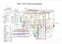
.. .72-xs2-circuit-diagram-b11325607311619 Colour aaaaa G Text 15 a1  RobinC.jpg
 
Last edited:
Well, foo. I put comments in the other thread, so I'll copy them here.

You found the missing front stoplamp switch. Good.

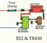
The fusing for the battery is correct in the original diagram.
The battery is capable of dumping hundreds of amps to shorts in the wiring, so must be fused. The rectifier can only put out a dozen or so amps, not enuff to fry wiring or blow a fuse.
Like this:
XS2-TX650-Battery.jpg

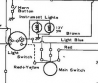
Wiring diagrams for these early models have a problem depicting the blue taillight wiring. A bit confusing, but only the taillight is powered in the "park" position, yet it and the instrument bulbs are all powered when headlights are on. The factory diagram shows only the blue taillight wire coming from the ignition switch's "park" position, yet no provision to power the taillight with the instrument lights. I have yet to see a wiring diagram that explains this. I had this figured out long ago, but it's gone.

I see you've also modified the starter button.
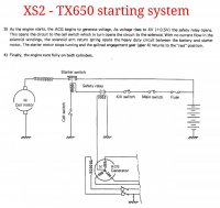
Here's another excerpt of the XS2-TX650 starting circuit, with the safety relay.

XS2-TX650-Starting.jpg
 
Last edited:
Sorry posted this thread long after i originally posted in the other XS2 thread.

I don't understand why there would be a brown wire from the safety relay to the R/W wire

Would the blue wire from the right bar switch on/of switch, connect up to the taillight off the Blue meter light circuit ??
 
Another snippet from the old manuals, attempting to show the goofy switch arrangement to manage the taillight power.
XS1B-Wiring2.jpg


Again, they still got it wrong. Notice the strange flippy contact in the "light switch". It's a failed attempt to depict the separation/connection of the two blue wires. The logic diagrams for the 70-72 (maybe 73) ignition and headlight switches are wrong, and their use of the red/yellow and (2) blue wires.

Been too long for me to remember. I rewired that mess outta mine back in the '90s. If I had an original 70-72 in front of me I could fix this mess...
 
...Would the blue wire from the right bar switch on/of switch, connect up to the taillight off the Blue meter light circuit ??

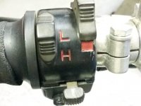
The XS2 used essentially the same headlight switch as the 70-71, on the left handlebar side. One slider for on/off, one for hi/low.
XS1B-LeftSwitch02.jpg

After 72, I'm rather clueless...
 
Something in the back of my head tells me that the red/yellow between the ignition switch and handlebar light switch doesn't feed power forward to the headlight switch. Rather, it feeds backward the instrument lighting power back to the ignition switch, which then powers the taillight.

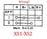
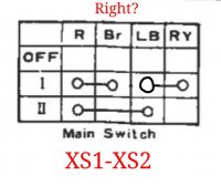
Edit: Take this with a grain of arsenic, but I believe that ignition switch logic table should be changed from this original version:
XS1-XS2-SwitchLogic01.jpg

To this version, showing how the blue wire is powered.
XS1-XS2-SwitchLogic02.jpg

Unfortunately, the last time I had an early ignition switch apart was in the '70s, but this seems to be what I remember...

EDIT2: Forget this post, it's all wrong...
 
Last edited:
I said right side bar switch............meant to say left........Yea right.........no left!..........right, left.........I give up........

looks like i might be right about the Blue wire from the Gauge light circuit heeds to go to the taillight blue wire.......Just need to understand there is a switch in that part of the diagram

later bikes have the on/off light switch on the right side bar switch and the high/low on the left.

I'm going to hit up mailman and try to get him involved and help with some continuity testing or whatever

Around the points area it was a bloody mess, got most of that sorted.........

Thanks Steve
 
Hey guys, I don't know the differences between the 72 and 73 in terms of wiring but I've got a relatively unmolested 73TX if there's anything I can check to help.
 
2Many, I think the original key switch diagram is correct. Position I is "On", position II is "Park". You don't want any lights being turned on in position I, which is what your "revised" diagram would do. Your "revised" diagram is how the '78 and later key switches are set up. The tail light comes on with the key, which is something I want to change.
 
I have 2 72s. Both have unmolested wiring.The one I picked up earlier this year does run. I checked how the ignition switch/headlight switch function. With ignition switch in position 1 headlight and taillight both turn on and off with the light switch on the left handlebar. Ignition switch in position 2 only the headlight turns on and off with the headlight switch, the taillight stays on full time. I thought that was how it worked but since I haven't ridden the other 72 since 1985 I thought I had better check and make sure.
 
Let me ask you this - do the instrument illumination bulbs come on in the "Park" position too, along with the tail light? The wiring diagram seems to indicate they will.
 
The operate like the taillight. Position 1 they go on and off with the headlight switch, position 2 they are on full time.
 
There is definitely a problem with the wiring diagram. It shows only 1 blue wire going from the ignition switch to only the taillight.
upload_2018-10-10_12-25-11.png
 

Attachments

  • upload_2018-10-10_12-26-19.png
    upload_2018-10-10_12-26-19.png
    381.1 KB · Views: 330
  • upload_2018-10-10_12-29-10.png
    upload_2018-10-10_12-29-10.png
    381.1 KB · Views: 385
Tried to add this. Still learning how to use the forum.
That is not true.There are actually 4 wires leaving the switch. I think if all the connections and the logic for the headlight switch was there everything would make a lot more sense.[/ATTACH]
 
I think this may be a bit more accurate. Shows 4 blue circuits.
upload_2018-10-10_12-43-53.png

The switch logic looks a bit funky. I've never seen a switch drawn like that.
 

Attachments

  • upload_2018-10-10_12-43-38.png
    upload_2018-10-10_12-43-38.png
    38.9 KB · Views: 279
Thanks for the imput........Good to make a clear defined diagram

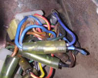
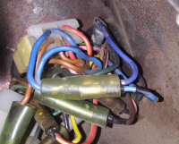
GLJ Thanks, any chance of a shot of the headlight workings with the wires opened up a bit more

didn't realize you had done a switch repair tutorial G........bookmarked......... helps a lot

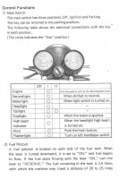
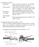
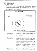
Post up these i found going through the XS2/TX owners manual...Clear description of the key position and what it operates
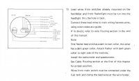
72 XS2 Riders Manual 06 Ignition switch.jpg 72 XS2 Riders Manual 07 Kill switch.jpg 72 XS2 Assembly Manual 10 Bucket wires.jpg

Switch testing..........Not a lot of relevance, just for my thinking
70-74 Service manual110 Ignition switch.jpg 70-74 Service manual110 Switch testing 1.jpg70-74 Service manual111 Switch testing 2.jpg
 
Back
Top