-
Enjoy XS650.com? Consider making a donation to help support the site.
XS650.com receives a small share of sales from some links on this page, but direct donations have a much greater impact on keeping this site going.
You are using an out of date browser. It may not display this or other websites correctly.
You should upgrade or use an alternative browser.
You should upgrade or use an alternative browser.
'75 650B Charging System Guidance Needed
- Thread starter REPETE
- Start date
REPETE
XS650 Addict
I'm on it and will report back.
Thank you.
Just one question before starting.
Prior to my rotor going bad, everything was fine (on the original regulator & rectifier)
Is it the electronic version more sensitive to variances?
Thank you.
Just one question before starting.
Prior to my rotor going bad, everything was fine (on the original regulator & rectifier)
Is it the electronic version more sensitive to variances?
So you are saying the old setup did work
Why not then connect the old regulator see how much that one gives
It is possible to adjust .
( It has some advantages and can be used for testing and fault finding being more robust
I would not use it ..but for test )
I would check its specs according to the service manual before connecting
Why not then connect the old regulator see how much that one gives
It is possible to adjust .
( It has some advantages and can be used for testing and fault finding being more robust
I would not use it ..but for test )
I would check its specs according to the service manual before connecting
Attachments
REPETE
XS650 Addict
I futzed with it trying to adjust it thinking it was my problem and then decided it just wasn't working... thus the replacement regulator/rectifier. It's probably way out of adjustment now but your thoughts are definitely worth consideration. I'll need the lift b/c I don't bend or get up off the floor too well so it'll take me a bit to clean up the parts that are spread out from another project and then run through the exercise.
I shall report back
Good info. guys... know that you're appreciated
I shall report back
Good info. guys... know that you're appreciated
Yes Sir
There are other options .. but since there is only one fuse ..the other options are more risky than retry the stock one
for now as first step.
But with some patience and cooperation we usually find it
There are other options .. but since there is only one fuse ..the other options are more risky than retry the stock one
for now as first step.
But with some patience and cooperation we usually find it
REPETE
XS650 Addict
Hello All
I had a bit of an absence and now have a bit of time to update.
I haven't yet cleaned up the ignition switch nor put the original rectifier & regulator back in place for a test. That ignition switch cleanup is something I definitely don't relish having to do... it's a task that kind of scares me But nonetheless, it's now in my head that the resistance could be better with there being a 1/2v loss through it so ultimately it's a task I'll need to tackle regardless.
Also, because of not having had time to deal with much of anything the past couple of weeks (i.e. reinstall the old rectifier and regulator for testing) I wanted to at least do something in regards to working towards a solution, so I did one thing that I felt made sense. I pulled out the solid state Electrosport Regulator and returned it to the mfg. for an exchange. Here was my rationale:
With a newly rebuilt rotor that's performing within specs (5.2ohm?) and all other things being equal... there were no modifications or changes to the wiring and the only equipment difference was the addition of the Electrosport Regulator... then by process of elimination, it (the Electropsort) had to be at fault. And I was right. They received it, tested it and ultimately declared it defective. A new replacement is on it's way and should be delivered today.
With some luck I can at least "get back to even" with a running bike that's charging properly and go after the ignition switch when time is more favorable.
More to come
I had a bit of an absence and now have a bit of time to update.
I haven't yet cleaned up the ignition switch nor put the original rectifier & regulator back in place for a test. That ignition switch cleanup is something I definitely don't relish having to do... it's a task that kind of scares me
But nonetheless, it's now in my head that the resistance could be better with there being a 1/2v loss through it so ultimately it's a task I'll need to tackle regardless.Also, because of not having had time to deal with much of anything the past couple of weeks (i.e. reinstall the old rectifier and regulator for testing) I wanted to at least do something in regards to working towards a solution, so I did one thing that I felt made sense. I pulled out the solid state Electrosport Regulator and returned it to the mfg. for an exchange. Here was my rationale:
With a newly rebuilt rotor that's performing within specs (5.2ohm?) and all other things being equal... there were no modifications or changes to the wiring and the only equipment difference was the addition of the Electrosport Regulator... then by process of elimination, it (the Electropsort) had to be at fault. And I was right. They received it, tested it and ultimately declared it defective. A new replacement is on it's way and should be delivered today.
With some luck I can at least "get back to even" with a running bike that's charging properly and go after the ignition switch when time is more favorable.
More to come
REPETE
XS650 Addict
New regulator arrived.
It made an improvement, but not to the point I'd feel comfortable using the bike till I get around to dealing with the ignition switch.
Currently getting:
at idle 14.03v
at 4k rpm 15.25v
Lower, but not correct. I'm hopefully going to get into the switch before the weekend is out... but I need to read through the thread http://www.xs650.com/threads/ignition-switch-overhaul.46712/ first.
More to come - thanks for the outlet
Well this is some type of progress 3 regulators and to high charging a first assumption is as mentioned
wrong physics in to the regulator.
I have been in to these ignitions lock for service myself with must I admit poor results
here might be fine instructions.
I have seen items for sale on e -- .bay new for not that much money ( for a rich man )
I got my lock working but I was on the verge to buy a replacement
If you google and someone else comes in about quality and so ..
Search e -bay for
ignition svitch xs 650
If you still have the original '75 key switch, it won't come apart quite the same as the Special switch in your link. It's not screwed together but rather the contact plate is simply crimped into the bottom of the switch housing .....

Bend the tabs outward and it should pop right out.
Bend the tabs outward and it should pop right out.
REPETE
XS650 Addict
Always good to know the path ahead... Thanks 5T
I have another conundrum
Work on bike tonight or go to free Foghat Concert up the road hmmmm LOL
I have another conundrum
Work on bike tonight or go to free Foghat Concert up the road
hmmmm LOLI'm still trying to wrap my head around that. I didn't think it was possible for a stock XS charging system to put out that kind of voltage at idle.Currently getting:
at idle 14.03v
On mine... with one of my rewinds... I'm lucky to get up to battery voltage at idle.... usually about 12.4...12.6V. at 1200rpm.
Yes, and the 15.25 volts when revved, I think that's still too high. Maybe you can test with the ignition switch bypassed temporarily, basically with the bike "hot wired". That would tell you if the ignition switch with it's voltage drop is the cause for the high charging output.
REPETE
XS650 Addict
I'm absoluteley the last guy to explain it... just the messenger.


BUT, thinking out load (sort of speak) is the regulator adding a 1/2v to adjust for the 1/2 volt loss? Adjusting for that 1:1 that'd make the idle charging voltage 13.53 and at higher rpm's at 14.75v That would be perfect, right?
Coincidence?
Regarding the hot wire test.... I'm interested and all ears .
What's involved?
Last edited:
Unplug the ignition switch (to remove it from the system) and in the harness plug or individual wires, jumper the red power in from the battery to the brown power out to the bike. Don't let it set like this long not running. The bike will be turned "On" and the coils will be getting charging voltage. Normally they release this voltage every time they fire a plug but if the bike isn't running, they'll keep charging and charging. They can overheat and burn out.
Without me going back through this thread... is that the only meter you measured with?
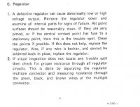
Well I did not Believe i would say this But the stock regulator is adjustable and robust
I don't trust it but have seen others here that do.
Say if it is a rotor a bit out of spec ---rewound ????
If points is used ( no electronics that can fry ) and a Voltmeter is installed. Provided the adjustment range is sufficient
on the regulator --- that can be a way forward at least as a temporary solution.
If senior enthusiasts here trusts the stock regulator perhaps that can be a solution.
REPETE
XS650 Addict
Jim - it's the only one I used with the replacement regulator. Prior, when problem was first identified, you had me dbl. check by using a second meter and the difference was neglible.
Jan - it's the original rotor rebuilt (re-wound).
Still using points
Has led signals, taillight and gauge lights.
I wouldn't object to using original regulator (as a last resort) but something is amiss and I'd sure like to find out why.
Jan - it's the original rotor rebuilt (re-wound).
Still using points
Has led signals, taillight and gauge lights.
I wouldn't object to using original regulator (as a last resort) but something is amiss and I'd sure like to find out why.
Jim - it's the only one I used with the replacement regulator. Prior, when problem was first identified, you had me dbl. check by using a second meter and the difference was neglible.
Jan - it's the original rotor rebuilt (re-wound).
Still using points
Has led signals, taillight and gauge lights.
I wouldn't object to using original regulator (as a last resort) but something is amiss and I'd sure like to find out why.
A rewind can like all other human endeavors go wrong The rumor was that it only last a couple of years
But that was most likely because of people here was doing a quick Half A** job
Myself did actually ask the staff at the closest auto electric shop If he was not interested in helping out out perhaps there is someone else
I have not been there after that... him confused over his profession not realizing he is not a cop.
Then about the stock regulator
It should be plug and play for testing
And if one want to " Hot Wire " I believe there is simpler solutions
If i recall right there are 3 wires into the regulator
One must be the actual voltage one is the feed to the rotor winding
Brown Black and Green
I am thinking separate wires to + Brown on battery and Black to Minus on battery
and green as before to rotor.
Please don't do it just yet ... especially not with the electronic regulators they fry quickly
let other have time to come in especially if they trust the old regulator and have any knowledge of adjustment range
There are also service manuals to find there
https://thexscafedotcom.wordpress.com/2011/01/10/xs650-manuals/
Test procedures for the Rotor / Stator / Regulator ---Resistance on rotor could be a first.
REPETE
XS650 Addict
Jan_P - "..... knowledge of adjustment range"
Yes! I had futzed with it prior to removing it and don't recall how much I turned the adjusting screw.
Yes! I had futzed with it prior to removing it and don't recall how much I turned the adjusting screw.
Similar threads
- Replies
- 13
- Views
- 422