Advice? Hairy electrical situation - new owner of 1982XSJ 650 project

JayR

XS650 Addict
Messages
335
Reaction score
118
Points
43
Location
CT
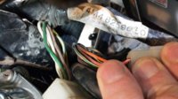
Gents (ladies), I would be grateful for your assessment: the first issue I am tackling is to get the electrical start/push button to work. I found the correct wiring diagram in my Haynes manual, and started tracking the wires back from the right side controls. Connections in the headlamp seem OK.

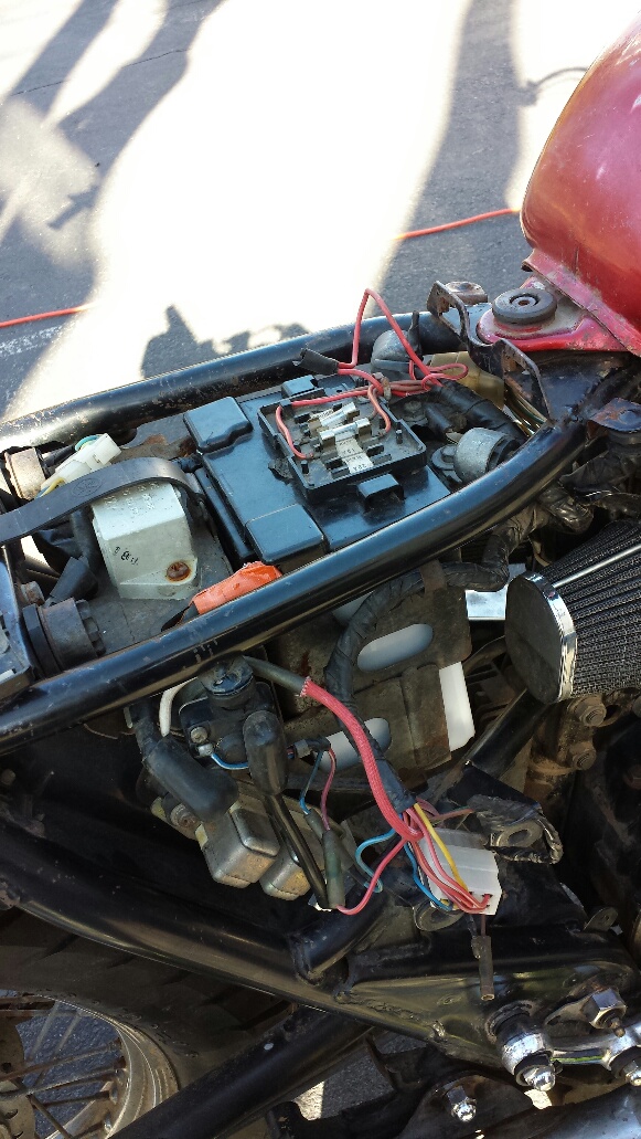
But a big mess in the fuse box, and the starter lockout relay connections are melted.

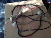
So this is bigger than just the push starter (turn signals did not come with bike btw) I'm up for the challenge: would replacing the fuse box with this one from Mike's be a good idea? http://www.mikesxs.net/product/10-2006.html

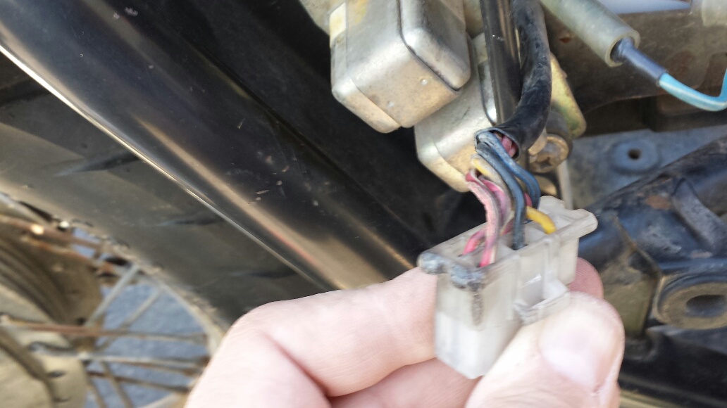
Should I go for a new Starter Relay http://www.mikesxs.net/product/24-6526.html
Harness http://www.mikesxs.net/product/24-6583.html which includes the fuse box?

This is a bit of a hairy mess so any experiences or advice that you can provide is appreciated!!
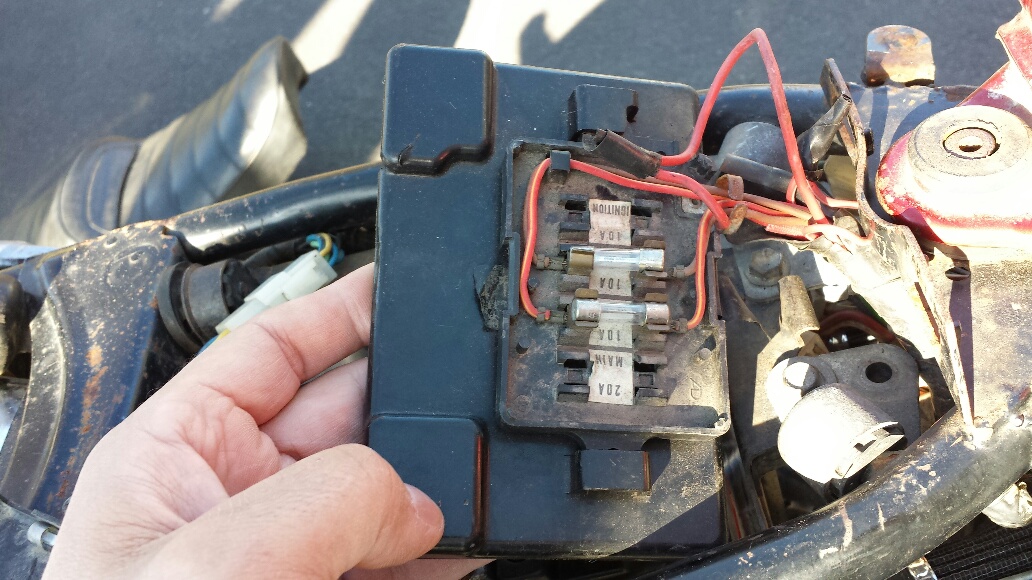

full


full


full
 
I'd go for a new wiring harness or make a custom harness.
 
Looks like a fuse kept blowing so the PO just tied the wires together. Obviously the problem wasn't solved and moved it along.

It is better to replace the fuse block with some sort of blade fuse setup. If you buy a nice block set of 4 then you can use it later in the rebuild. I bought 4 individual ones and wired/soldered them into the wires coming in and out of the fuse block.

That connecter can be repaired/replaced but it might pay to have a good look at the loom and decide if repairing is worth it, or go in another direction.

Note; The whole loom needs to be gone through from one end to another cleaning all bullet connectors, couplings and cleaning any earth connections, and making sure the all grounds are against clean metal. Test for continuity when doing this also for any broken or suspect wires.

Good link for wiring harness musings
 
Good link for wiring harness musings[/QUOTE]

Thanks AZMAN and Skull650 - the current harness is in rough shape, I'm going to get a new one and replace fuses with a new ATM fuse blade. Then once I make the new connections I'll know which circuits are the biggest problems and then isolate from there. I'll be popping a lot of fuses to start I think, but the Wiring Musings link had a lot of excellent ideas on testing and isolating. So one step at a time. I'll tackle the starter lockout relay during that process I believe.
 
Just buy some in line fuse holders and start with 15 am fuses. Don't go to big because you may start to burn wires up before fuse blows. I make harnesses up for stock and choppers so you can contact me at DADDYGCYCLES@YAHOO.COM anytime and I can walk you threw some problems you may come up with. Your best bet would be to try and buy a good used harness if you are going to keep all the relays.
Rich

Thanks Rich - just sent you an email.
 
I spent some time today with my Haynes manual opened to the 1982 XS 650 SJ/SK model wiring diagram. The model codes on my frame and engine match that model year 5V4. I took the seat and tank off, and began inspecting the harness starting at the ignition coil, flasher relay, cancelling relay and horn. It looks OK there.

I then made my way back towards the starter switch, looking at the individual wires, then the diagram, then the wires again to familiarize myself with each part, coupling, it's function, and condition.

As mentioned, the fuse box is blown, with the ignition wires spliced together to bypass the wrecked terminals. But I spent some time learning where the R, R/Y, Br, and R/W fused wires go etc.

Here's where it gets interesting: upon further inspection i discovered that the harness tag is from a 1980-81 XS SH and is labeled with that model code 4M4.

Since the 1980-81 models do not have all of the extra safety relays like the side stand switch and the clutch switch, (other?) my hypothesis is that the PO slapped the wrong harness on (he had 2 disassembled bikes that he started with, the other was a 1980), therefore the side stand and clutch circuits were not hooked up, and as a result the engine would not turn over. The PO then jumped the ignition terminal to bypass the side stand and clutch relays. This allows the bike to be started with the kick start, but not the push button, and also led to the issue of the Starting circuit cutoff relay melting.

Is that plausible? If the side stand and clutch switches are not connected to the harness, then the bike will not start - is that correct?

The 1980-81 and 1981-82 harnesses are very similar with the exception of the side stand switch, clutch switch, I believe changes to the headlight relay, and maybe the safety relay and starting circuit cutoff relays.

Should I get a new 1981-82 5V4 harness and start from scratch, or can I make the 80-81 harness work to the point of getting the push start to function?

I can do without the side stand and clutch switches if the 4M4 harness can be made to work. In fact, even if I had the correct 5V4 harness I would like to eliminate these switches. I think the neutral safety switch is enough. Any feedback from the forum members would be appreciated as always.
 

Attachments

  • image.jpg
    image.jpg
    184.7 KB · Views: 546
If the bike is a 80 to 83 with TCI IGNITION all you need to do is find the hot wire to the TCI and coil it maybe just red or red/white and feed 12 volts to it without touching anything else and bike will fire up if all good.
Here is a picture of a stripped down harness and you can see the red/white wire. This is both for charging and for the TCI to coil
This is from a 1981 harness . AS you can see
RED/WHITE 12volts
BLUE NEUTRAL LIGHT
BROWN goes to ignition switch
BLACK ground
The rest are the plugs
 

Attachments

  • 2014-03-27 09.36.02.jpg
    2014-03-27 09.36.02.jpg
    197.8 KB · Views: 317
If the bike is a 80 to 83 with TCI IGNITION all you need to do is find the hot wire to the TCI and coil it maybe just red or red/white and feed 12 volts to it without touching anything else and bike will fire up if all good.
Here is a picture of a stripped down harness and you can see the red/white wire. This is both for charging and for the TCI to coil
This is from a 1981 harness . AS you can see
RED/WHITE 12volts
BLUE NEUTRAL LIGHT
BROWN goes to ignition switch
BLACK ground
The rest are the plugs

Yes it is A TCI ignition and the Ignitor unit and ignition coil both have a RED/WHITE wire leading from the harness. But the wires are attached via the connectors compared to your harness where the wire is more accessible if I have it right.

Nice harness btw. Can you make one for my 82 that would work without the side stand relay and clutch relay, and still let everything else function properly - turn signals, push start, hi/lo beam, neutral safety switch, brake lights etc?
 
I can make you a custom harness with your parts for $150.00
Your handlebar controls
Your Altenator/reg/rec/Tci/Coil
Custom to your bike
or
If you just want to start your bike the harness in picture is on EBAY for sale
 
Thanks DGC - i am more in just starting the bike mode now, but the longer term plan once I get it road worthy and work out the bugs is to do a build. At that point I may be in need of a custom so thank you for the offer. Is the one pictured under DG cycles on ebay?
 
I spent some time today with my Haynes manual opened to the 1982 XS 650 SJ/SK model wiring diagram. The model codes on my frame and engine match that model year 5V4. I took the seat and tank off, and began inspecting the harness starting at the ignition coil, flasher relay, cancelling relay and horn. It looks OK there.

I then made my way back towards the starter switch, looking at the individual wires, then the diagram, then the wires again to familiarize myself with each part, coupling, it's function, and condition.

As mentioned, the fuse box is blown, with the ignition wires spliced together to bypass the wrecked terminals. But I spent some time learning where the R, R/Y, Br, and R/W fused wires go etc.

Here's where it gets interesting: upon further inspection i discovered that the harness tag is from a 1980-81 XS SH and is labeled with that model code 4M4.

Since the 1980-81 models do not have all of the extra safety relays like the side stand switch and the clutch switch, (other?) my hypothesis is that the PO slapped the wrong harness on (he had 2 disassembled bikes that he started with, the other was a 1980), therefore the side stand and clutch circuits were not hooked up, and as a result the engine would not turn over. The PO then jumped the ignition terminal to bypass the side stand and clutch relays. This allows the bike to be started with the kick start, but not the push button, and also led to the issue of the Starting circuit cutoff relay melting.

Is that plausible? If the side stand and clutch switches are not connected to the harness, then the bike will not start - is that correct?

The 1980-81 and 1981-82 harnesses are very similar with the exception of the side stand switch, clutch switch, I believe changes to the headlight relay, and maybe the safety relay and starting circuit cutoff relays.

Should I get a new 1981-82 5V4 harness and start from scratch, or can I make the 80-81 harness work to the point of getting the push start to function?

I can do without the side stand and clutch switches if the 4M4 harness can be made to work. In fact, even if I had the correct 5V4 harness I would like to eliminate these switches. I think the neutral safety switch is enough. Any feedback from the forum members would be appreciated as always.

5V4 and 4M4 are almost identical. The only difference is the side stand relay and wiring to the side-stand. It shouldn't make any difference to your bike starting, if the relay isn't there.

A link to the wiring diagram thread, scroll down to post 7 and there is a full set of diagrams in color
 
Back
Top