Another wiring question

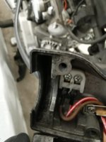
Programming was a snap!! .... However rear light still doesn't work. I connected a signal light to the munit output for brakes and it works - I may need to buy a new taillight..

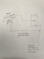
The kill switch is stumping me. There are 3 wires Red, blue and Brown. Blue goes to munit input. I got that.
I put the Red/white to brown (munit aux).
Brown I connected to coil.

When I press the start button - it's engaging and about to start. However it's about to start when the switch is in Run or Kill. ?? It engages in both settings....

Should one of them be going to the Aux input?

How do I figure out which way to have the kill switch engaged.
 

Attachments

  • IMG_20191223_125052.jpg
    IMG_20191223_125052.jpg
    116.6 KB · Views: 162
Try this:
Start Button:
Blue wire to M-Unit Start In
Switch grounds to handle bar - make sure you have continuity between the handlebar and the frame and that the frame is grounded
One solenoid wire goes to Start Out
One solenoid wire goes to ground
Kill Switch:
Red/White to Aux out
Brown to coil and ignition unit
If I recall correctly the stock switch doesn't ground the coil but rather provides power to the coil
The M-Unit Kill In and Ignition Out are not used
 
So I don't input anything into m_unit config for kill switch? Weird because munit manual has the kill switch wired to confirm. I will leave open.

Red/white to aux is the ignition power (which on my bike is brown) and I will connect that.

My coil has a red/white and Orange wires. Do I go brown to red/white? When I traced the coil red/white, if I can remember , it connects to coil and ignition unit. Is there a specific place to have the brown connect, or can I just connect it anywhere on the red/white between coil and ignition unit?
 
Try this:
Start Button:
Blue wire to M-Unit Start In
Switch grounds to handle bar - make sure you have continuity between the handlebar and the frame and that the frame is grounded
One solenoid wire goes to Start Out
One solenoid wire goes to ground
Kill Switch:
Red/White to Aux out
Brown to coil and ignition unit
If I recall correctly the stock switch doesn't ground the coil but rather provides power to the coil
The M-Unit Kill In and Ignition Out are not used
So you recommend to have the +12VDC to the coils go via the kill switch, just like the stock setup? That may result in a undesired voltage drop to the coils, and a weak spark. What about using the dedicated M unit channel, this way: +12VDC from ignition lock out to kill switch, just like stock, "run" position gives +12VDC out from kill switch. Then use a 5 pin automotive (Bosch) relay to invert that signal. +12VDC from kill switch to #86, #30 and #85 connected to ground, and #87A to kill input on M unit. Then the coils receive +12VDC only when ignition switch is "on" and kill switch is on "run", directly from the "ignition" output on the M unit. A smaller relay with the same "backward" function as described can also be used. It just needs to be normally closed, and open when activated. These micro relays should be fine for this purpose:
https://www.ebay.co.uk/itm/5-x-12V-...-1ff14909df3b&epid=1143738321&redirect=mobile
 
Last edited:
Chachiboy. Do you have the same m-unit that I posted a picture of? If not please post a picture of yours.

I wired my kill switch as per the post above to work around the stock switch.

ArcticXS - as you gathered the stock switch will ground (kill) when in run position and run when in the off position. What manual are you looking at? None that I have looked at show the kill switch wired to the m-unit ignition lock terminal.
 
Yes my M-unit is exactly like the one in the drawing. Only difference in set up is I have the stock ignition unit and regulator/rectifier
Your drawing has Brown from kill switch connected to these. I haven't tried this yet as I am unsure where to connect it. The manual shows the kill switch wired to Config input (?)
 
Try connecting one kill switch wire to the m unit config and the second kill switch wire to ground.

Connect the ignition system to the m unit aux terminal.

This is how the m unit manual shows the connections. It should work but the switch run position will kill the ignition and the switch off position will allow the ignition to engage.
 
Chachiboy.
ArcticXS - as you gathered the stock switch will ground (kill) when in run position and run when in the off position. What manual are you looking at? None that I have looked at show the kill switch wired to the m-unit ignition lock terminal.
By using a NC (normally closed) relay, controlled by the kill switch, you can invert its function. Instead of supplying 12VDC to the coils when ignition switch is on, and kill switch is in run, the relay will connect the "kill" input to ground, unless ignition lock is on and kill switch is on run. Only then will the "kill" input be disconnected from ground.
The reason for me posting this, is that it is a well known problem with voltage drop in the oem configuration. And many, including myself, have added a relay that supplies the coils directly from the battery, and using the original switched supply to the coils for controlling this relay. With an M unit, the power is switched by the unit, the relay is only there to change the "signal" from the kill switch to one that works with the M unit.
 
Arcticxs thanks for this insight. I have read your recommendation several times but I am a visual person and still don't fully understand the relay wiring.

Peterg any chance you can send me a drawing of how you did it after you make the change?
 
I'm wondering if you are caught up in the differance between CDI and TCI ignitions. TCI systems power the coil from the kill sw. CDI the kill switch grounds out the coil input to stop the engine. TCI systems cutoff power to the coils.
 
I'm wondering if you are caught up in the differance between CDI and TCI ignitions. TCI systems power the coil from the kill sw. CDI the kill switch grounds out the coil input to stop the engine. TCI systems cutoff power to the coils.
Actually, it is the difference between any self powered/magneto ignition, and any battery powered ignition. Whether it is TCI, CDI or points does not matter. My posts in this thread are all based on battery powered points or electronic ignition (Pamco, XsCharge, Boyer, Dyna et al)
 
This is what I think ArcticXS suggested:

m-unit aux terminal > kill switch brown wire
kill switch red/white wire > relay 86 terminal
m-unit config terminal > relay 87a terminal
relay 30 terminal > ground
relay 85 terminal > ground
relay 87 terminal > not connected

8AD62E5A-21EB-4F85-9A70-D05FDABCA627.jpeg
 

Attachments

  • 1F3CAFCD-AF99-41E1-9264-3D0BEAEB6A46.jpeg
    1F3CAFCD-AF99-41E1-9264-3D0BEAEB6A46.jpeg
    91.3 KB · Views: 135
Last edited:
This is what I think ArcticXS suggested:

m-unit aux terminal > kill switch brown wire
kill switch red/white wire > relay 86 terminal
m-unit config terminal > relay 87a terminal
relay 30 terminal > ground
relay 85 terminal > ground
relay 87 terminal > not connected

View attachment 156703
I have not received my M Unit yet, so will have to ask. Why do you power the ignition from the Aux channel?
I have all the way assumed that the "Ignition Out" would be on, only when the "kill switch" input was not connected to ground, and the +12VDC from ignition lock to M unit was on. And that coils and any electronic ignition black box was powered from "Ignition out"
Maybe you can confirm the relationship between "kill switch" input and the "ignition" output channels? When do you get +12VDC out, with "kill switch" grounded or not grounded?
 
ArcticXS. If the ignition system positive is directly connected to power and system ground is switched would there be a voltage drop issue?
No, if the coils (and "black box" if electronic ignition) are supplied from the Aux out on the M-unit, and the cabling is 1.5 sq.mm or heavier, the voltage drop should be minimal. I am not sure what you mean by system ground being switched, though. The relay provides the "grounding" of the M Unit input, in order to switch the output to on.

The problem with voltage drop is caused by the rather convoluted path for power (+12VDC) to the coils, when using a stock, or modified stock setup. Basically from battery, via fuse, to ignition lock. Then from ignition lock to kill switch, back to headlight, before arriving at the coils. That is 2 switches, a lot of connectors, and one fuse. Plenty of potential for extra resistance, causing voltage drop. Also, the stock wiring is pretty light, which also adds to the issue. Using aftermarket coils with a lower primary resistance just makes it worse.

When bringing my 1977 XS out of a 7 year hibernation last spring, I had to clean all connectors, and switches to get halfway acceptable voltage at the coils. So I ended up installing a relay next to the coils, supplied directly from the battery via a 10A fuse and the shortest possible 2.5mm2 wire. But soon I will rewire the entire bike, with a M Unit, and a Powerdynamo/ Vape PMA. But the goal remains the same, minimal voltage drop at coils and also at headlight bulb. (In addition to a more streamlined wiring arrangement, of course)
 
Back
Top