Graeme1198
XS650 Enthusiast
Hi guys,
So I’ve had a few issues with my charging system.
It’s an 82 so the headlight is linked into the system so I know I’ve got problem.
I’ve been referred to the tech page where the very thorough list of electrical faults was very helpful, but I’m still not able to get it going.
I’ll go through the list of what I’ve done with my results....
Battery is good, 12.6v left a signal running for 20 mins or so and camp back and still up at 12.4v charge up again to 12.6v
Fluids topped up in battery I’m happy that’s ok.
Slap test, Poor have to take the cover off to stick and even then it’s about 2-3mm away from the rotor nut. Is not different magnetic field with the ignition on or off.
New brushes.
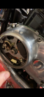
Rotor is clean.
Green reg/Rec wire to ground, no change in voltage. Even with rpm up.
Brown wire voltage test on brush, 12.4v the same as the battery.
Rotor ring test: 5.3 Ohms
Ring test to ground: infinity
I can bypass the B/BL and the R/W on the connections to the relay to get the headlight to turn on, it will turn on and stay on, I can then ground it to switch it off. So I know the headlight circuit is ok.
Does anyone have any more things I could try?
Thanks guys.
So I’ve had a few issues with my charging system.
It’s an 82 so the headlight is linked into the system so I know I’ve got problem.
I’ve been referred to the tech page where the very thorough list of electrical faults was very helpful, but I’m still not able to get it going.
I’ll go through the list of what I’ve done with my results....
Battery is good, 12.6v left a signal running for 20 mins or so and camp back and still up at 12.4v charge up again to 12.6v
Fluids topped up in battery I’m happy that’s ok.
Slap test, Poor have to take the cover off to stick and even then it’s about 2-3mm away from the rotor nut. Is not different magnetic field with the ignition on or off.
New brushes.
Rotor is clean.
Green reg/Rec wire to ground, no change in voltage. Even with rpm up.
Brown wire voltage test on brush, 12.4v the same as the battery.
Rotor ring test: 5.3 Ohms
Ring test to ground: infinity
I can bypass the B/BL and the R/W on the connections to the relay to get the headlight to turn on, it will turn on and stay on, I can then ground it to switch it off. So I know the headlight circuit is ok.
Does anyone have any more things I could try?
Thanks guys.
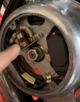
") Amazing what a pic can show us. You're inner brush is 180 out and not connected.
Amazing what a pic can show us. You're inner brush is 180 out and not connected.