Bizarre TCI problem, short video

dog bunny did you checked the neutral switch for a short when activated I have a few in the past when I worked for yamaha.just wanted to know so I can put in the memory file.the shorted ones we had was neutral light on all the time not a stalling problem.
 
Here's the ignition interrupt circuit for the 82-3 J-K models.

full
 
Dirtyy Dog, thanks for the help and suggestion, but the neutral light switch, the neutral light and the neutral light wiring were/are all good.

gggGary, I liked the first diagram that you posted before you edited your post better, this one:

full

and your idea that maybe the diode was bad. Who knows? I really don't remember if the bike had a clutch safety switch, and if it did, I don't remember how I disabled it, whether by removing the relay or by simply jumpering the switch. Furthermore, I cannot for the life of me figure that drawing out -- I'm not very smart, but I think the drawing and the description are wrong.

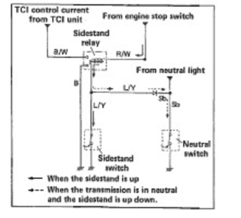
The same goes for the drawing with the sidestand switch you posted. I don't remember if the bike had a sidestand safety switch, and if it did, I don't remember how I disabled it. And, I can't figure out that drawing either.

In any case, those were great ideas, and I thank you, but I assume that they referred to the problem that I had when shifting out of neutral that I had two years ago.

xs650.jpg

The current problem, described in this thread's initial post, is a spark problem, it is on a different bike, and that bike has been re-wired similar to the simplified diagram above. All safety relays, and associated wiring, switches, and diodes are long gone. I said it is wired similar to the above diagram -- I do have a horn, and a neutral light, and two brake light switches, and no power outlet.
 
Heck yeah. I knew that diagram was wrong. I literally spent an hour last night trying to figure it out, and I finally decided that it didn't make sense.

I'm still having a little problem with the revised diagram. The top correction in red, the one labeled "Safety Relay" -- that looks like a switch to me, not a relay. Is it operated by the Starter Lockout Relay -- when the Starter Lockout Relay coil is energized, does it close TWO switches -- the switch right next to it in the drawing in the dotted line box, AND the red switch that is labeled "Safety Relay"?

Furthermore, this is the thing that really confuses me in both diagrams: the switch labeled "Starting circuit cut-off switch" -- that's the switch on the clutch lever, correct? And when you pull the clutch lever, that switch closes, correct? If so, then every time you pull the clutch lever, the neutral light comes on -- the circuit would be: Battery - Main switch - Neutral indicator light - diode - Starting circuit cut-off switch - ground.
 
The drawing above from the Haynes manual is incorrect. Here is a correction in red:

untitled.jpg

That drawing is from the Yamaha supplement for the 82 -83 bikes not Haynes, doesn't make it right but it is official....LOL

Yeah DB I was riffing off the 'other weird problem. My experience with electrical is limited to burning up wires, but the continuous spark at intervals suggests a capacitor charging up and causing it to fire? Electric fences work like that, the voltage slowly climbs till the fence finally selects the best path to ground and arcs to it.
 
Heck yeah. I knew that diagram was wrong. I literally spent an hour last night trying to figure it out, and I finally decided that it didn't make sense.

I'm still having a little problem with the revised diagram. The top correction in red, the one labeled "Safety Relay" -- that looks like a switch to me, not a relay. Is it operated by the Starter Lockout Relay -- when the Starter Lockout Relay coil is energized, does it close TWO switches -- the switch right next to it in the drawing in the dotted line box, AND the red switch that is labeled "Safety Relay"?

Furthermore, this is the thing that really confuses me in both diagrams: the switch labeled "Starting circuit cut-off switch" -- that's the switch on the clutch lever, correct? And when you pull the clutch lever, that switch closes, correct? If so, then every time you pull the clutch lever, the neutral light comes on -- the circuit would be: Battery - Main switch - Neutral indicator light - diode - Starting circuit cut-off switch - ground.

The drawing is not a complete schematic of the electrical system. The added contact in red is a contact from the safety relay. The bottom relay is the starter lockout relay, not the safety relay. This drawing does appear in the Haynes manual but was probably just a copy of the official drawing in the Yamaha manual.
 
this is the thing that really confuses me in both diagrams: the switch labeled "Starting circuit cut-off switch" -- that's the switch on the clutch lever, correct? And when you pull the clutch lever, that switch closes, correct? If so, then every time you pull the clutch lever, the neutral light comes on -- the circuit would be: Battery - Main switch - Neutral indicator light - diode - Starting circuit cut-off switch - ground.

That revised "starter lockout relay" diagram is more or less correct. But it is the "safety relay". The switch labeled "safety relay" is SR, Starter Relay, from the SR/LR double relay board. Note that though it's called SR, Starter Relay, the actual starter relay of the kind we're all familiar with is called "Starter Switch" in the diagram.

Regarding the neutral light and the switch, there's no path to ground for the light that is depending on the clutch switch; due to the diode, which opposes it. In fact one thing that was wrong with Ol' Trigger originally was this diode was shorted internally so when I pulled the clutch the neutral light did come on. Checking the relay with a meter I figured out what was going on, broke the relay open and replaced the diode with some Radio Shack fare and all was good. Soon the clutch swhich broke at the handlebar so I cut it off and twisted it together inside the headlight bucket so the clutch was always "pulled". Sometime after that I realized that meant this relay was always energized, which was unnecessary, so I pulled the relay and just twisted together the two R/W wires.
 
Okay, thought I'd wrap this one up.
I never did find the problem.
Keep in mind that while I am no PamcoPete, electricity is my specialty. Just take my word for this.
I tried everything that was suggested and more. I swapped TCIs, coils, and stator/pick-up assemblies. I checked rotor magnet strength on two different rotors that I tried. I ran new hot-wires directly from the battery to the coil and to the TCI, thereby eliminating the possibility of bad switches, fuses or wiring. I inspected, re-did and beefed up the entire ground system. I eliminated all of the white plastic factory connectors and their staked-on spade terminals, and direct soldered all TCI, coil, and pick-up connections (reg/rec connections too).

I do not believe that there is anything else that I could have done.

Symptoms that I have described before remained intermittent, temporary and unpredictable, coming and going without correlation to anything. The bike was a rolling time bomb, eventually I was going to loose spark at the worst possible time and get killed by a cage.

Worked on it on and off, mostly off over a period of 9 months. Would always attack it anew with a new idea or theory.

The Famous Limey, the local guru, kept on telling me to just install a Pamco. He said that it is cheaper for the customer for him to just put a Pamco in rather than try to fix a TCI problem that doesn't make sense. I did not want to just install a Pamco. I am a cheapskate, this TCI worked fine 99% of the time, this would have required the more expensive advance and rod installation, and most of all, I do not like being defeated by electricity, and I wanted to find out the problem.

But I never did find the problem, I installed a Pamco, and now the bike is instantly fixed and runs better too. SDhould have ionstalled the Pamco nine months ago.

My only regret is that when I swapped TCIs that I didn't try swapping a third TCI. That's the only explanation that I can think of -- that two TCIs were both bad in the same way. Those TCIs will eventually be tested on another correctly-running TCI bike that I have and I will report back again.
 
Last edited:
"Okay, thought I'd wrap this one up.
I never did find the problem."


Did you consult with Shaggy and Scooby? It could be a Red Herring.


Glad she's up and running, whatever it takes. Don't beat yourself up too bad about not finding " IT " .

Better off with IT gone. :thumbsup:
 
The bummer of it is that I tried so hard and learned absolutely nothing. I added zero to my knowledge base.
 
dog,

I know you're 'done' with this.....but I just wanted to chime in and say that I feel your pain!! These kinds of 'intermittent' and 'ghost in the machine' problems can be about as frustrating as it gets! In reading all your information, I have a 'theory' on both your original problem and the related symptom. Taking in to consideration that the coil is 'potentially' energized when ever the ignition key is 'on', the kill switch is 'on' and the fuses are good......that means that the ONLY thing that can cause that coil to generate a spark is the Ignition Module, as that's where the completion of the 'ground' side of the circuit is made.

I'm NOT an expert in these things....but from what I understand, there are some differences in what 'kind' of ignition you're dealing with. In the case of this Yamaha XS650 system.....it's a simple 'electronic ignition' where you simply use something like the pick-up on the rotor/stator as a 'trigger' switch....and you 'signal' the Ignition Module to switch 'ground' on and off to the coil.....thus completing the circuit. The Ignition Module uses the modern day semi-conductors.....or 'transistors'.......which are really nothing more than 'switching devices'.....and they are what do the 'make' or 'break' duty on the ground side. However, in order to accommodate the need for 'advance' in an ignition system, you have to incorporate both a 'clock' (or 'pulse counter)....and a pre programmed 'chip' that works with the clock ....and measures the speed of the pulses and then alters the 'moment' at which the switching takes place. That's the essence of a transistorized control module..... but as you can see, there are issues that can make it proprietary in nature.....where-by you simply can't substitute one type of module for another.

Anyway...... in order to generate spark....that module MUST be switching ground on and off. The 'rhythmic' nature of the spark pattern to me indicates that it's linked to the 'clock' that's built in to the module. So.....to me......a failure within that box would clearly explain that problem to me. Further.....consider that a solid-state device is not only a switching device....but also a 'current sensitive' device....... As such, the difference in load between using the starter vs using the kick may explain the 'no-spark' problem. When using the kick starter, the box was getting 'full' voltage..... When using the starter, the current draw from the starter may have been enough to NOT overload what ever was already failing in the ignition module. So....two of three problems explained.....or 'maybe' explained. But...what about problem 3: The fact that TWO Ignition Modules exhibited the exact same symptom?? Well......while I'd like to chalk that off to coincidence, my belief is that there IS (or 'was') a 'causal' issue some where within that motorcycle.....and that what ever it was; a short in the wiring harness, an over-charging from the reg/rec, a short in a battery cell...who knows..... But, what ever it was......it 'caused' the failure in the ignition modules.

NOW.....the only thing lacking here is the results of: Testing the 'pulled' Ignition Modules on other known good bikes. All I can say there is: If those modules DO work fine on other bikes....then your problem was a 'relationship' problem between the wiring harness, pickup, and the modules themselves.

I'm still incline to think you're right.....you had two 'bad' modules, or perhaps one could say; two modules that acted similarly on THAT motorcycle. But...I'd like to know just how they worked when tried on another known good motorcycle. Perhaps a 3rd IM would have eliminated the symptoms....... But, perhaps all the other 'stack up' of possible issues would have resulted in a 3rd module exhibiting the same symptoms again. Either way.......I'm glad you got it running with the Pamco unit. But, I'd still like to know what happened when the 'bad' units got tested on another bike. And, if you plan to 'scrap' either one of them, I'm looking for 'parts' units......so please, keep that in mind.

For what it's worth..........and thanks for letting me put my $0.02 in........

Tom D.


Tom D.
 
Back
Top