So I started on the process last week, and finished up over the weekend. Interesting exercise, there are a few things going on in there that aren't addressed in any of the data I've found on this repair. I'll run through my experience pic by pic.
Here's the hub prior to any work, note the broken spring.
http://s292.photobucket.com/user/patdepkin/media/DSCN0698_zpsdmdwxgh0.jpg.html
http://s292.photobucket.com/user/patdepkin/media/DSCN0697_zpsuew7ngbt.jpg.html?sort=3&o=34
Starting to drill the rivets. My cheap Harbor Freight drill press isn't the most precise, but I wouldn't recommend trying it free hand. I drilled a small pilot hole all the way through, that probably wasn't necessary.
http://s292.photobucket.com/user/patdepkin/media/DSCN0748_zpswyjizh1f.jpg.html?sort=3&o=30
Hub after getting it free of the gear.
http://s292.photobucket.com/user/patdepkin/media/DSCN0749_zps4rfeeuv8.jpg.html?sort=3&o=29
Here is the gear with the stamped steel cover plate removed.
http://s292.photobucket.com/user/patdepkin/media/DSCN0750_zpsis5pfkou.jpg.html?sort=3&o=28
And the stamped cover. Note the spacers on the rivet shafts, note the orientation(the fat part goes toward the steel plate).
http://s292.photobucket.com/user/patdepkin/media/DSCN0751_zps00tshcmb.jpg.html?sort=3&o=27
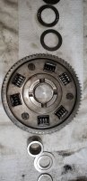
Here is the unit with the springs out in its original configuration.
http://s292.photobucket.com/user/patdepkin/media/DSCN0752_zps7qfkkdo8.jpg.html?sort=3&o=26
Steel plate prior to getting the spacers and rivets out. Note the steel gear and the slots that let the clutch basket move against the springs.
http://s292.photobucket.com/user/patdepkin/media/DSCN0754_zpsxsjp5dno.jpg.html?sort=3&o=24
This was new to me. When I was cleaning the aluminum basket of metal filings and oil, I hit it with the air gun and 2 washers/spacers blew into the dark recesses of the garage. Oops. I found 'em, and determined the orientation to be as follows. First, the flat spacer goes on the aluminum basket.
http://s292.photobucket.com/user/patdepkin/media/DSCN0765_zpsu4soirzn.jpg.html?sort=3&o=22
Then, the convex spacer goes on top of the flat one. I figured the orientation based on the shiny wear pattern on both the convex spacer and the steel gear.
http://s292.photobucket.com/user/patdepkin/media/DSCN0768_zpspsgelhnz.jpg.html?sort=3&o=19
http://s292.photobucket.com/user/patdepkin/media/DSCN0769_zpsc1vsfxfk.jpg.html?sort=3&o=18
Now we start on getting the springs in. The recesses in the aluminum basket are equal size, and the springs will have to be compressed a bit to get them in. A pair of slip joint pliers worked nicely.
http://s292.photobucket.com/user/patdepkin/media/DSCN0770_zpsvnarrtnr.jpg.html?sort=3&o=17
http://s292.photobucket.com/user/patdepkin/media/DSCN0771_zps4sefl2b7.jpg.html?sort=3&o=16
Once the springs are in, place the spacers(fat side up) in the slotted portion of the steel gear. 3 of the springs will not interfere with the gear, 3 will need to be compressed to fit in the steel gear slots. These 3 are the first to absorb driveline shock, then the other three start carrying the load.
http://s292.photobucket.com/user/patdepkin/media/DSCN0772_zpsk9ifcyny.jpg.html?sort=3&o=15
http://s292.photobucket.com/user/patdepkin/media/DSCN0774_zpsrlu9j9qs.jpg.html?sort=3&o=13
Getting the steel plate into place took a few tries. The springs need to be compressed for the plate to fit over them, and the plate needs to be fully seated before the bolts are installed. I ended up using the bolts to hold things in place while I used a screwdriver blade to get the springs home.
http://s292.photobucket.com/user/patdepkin/media/DSCN0780_zpsvk9zwgi1.jpg.html?sort=3&o=7
http://s292.photobucket.com/user/patdepkin/media/DSCN0782_zpsxwa2uigt.jpg.html?sort=3&o=5
After everything is home and happy, torque down the nuts and apply red loc-tite. Let cure as directed and then you are good to go. I couldn't get Allen head fasteners for the clutch spring bolt mod, so I went with regular hex heads. Worked fine.
http://s292.photobucket.com/user/patdepkin/media/DSCN0784_zps3vjhu393.jpg.html?sort=3&o=3
Buttoned everything up and have put maybe 50 miles on the bike, everything seems fine.
Well, I tried to get the images to show up, maybe one of the mods can fix it so they are visible rather than links.
Here's the hub prior to any work, note the broken spring.
http://s292.photobucket.com/user/patdepkin/media/DSCN0698_zpsdmdwxgh0.jpg.html
http://s292.photobucket.com/user/patdepkin/media/DSCN0697_zpsuew7ngbt.jpg.html?sort=3&o=34
Starting to drill the rivets. My cheap Harbor Freight drill press isn't the most precise, but I wouldn't recommend trying it free hand. I drilled a small pilot hole all the way through, that probably wasn't necessary.
http://s292.photobucket.com/user/patdepkin/media/DSCN0748_zpswyjizh1f.jpg.html?sort=3&o=30
Hub after getting it free of the gear.
http://s292.photobucket.com/user/patdepkin/media/DSCN0749_zps4rfeeuv8.jpg.html?sort=3&o=29
Here is the gear with the stamped steel cover plate removed.
http://s292.photobucket.com/user/patdepkin/media/DSCN0750_zpsis5pfkou.jpg.html?sort=3&o=28
And the stamped cover. Note the spacers on the rivet shafts, note the orientation(the fat part goes toward the steel plate).
http://s292.photobucket.com/user/patdepkin/media/DSCN0751_zps00tshcmb.jpg.html?sort=3&o=27
Here is the unit with the springs out in its original configuration.
http://s292.photobucket.com/user/patdepkin/media/DSCN0752_zps7qfkkdo8.jpg.html?sort=3&o=26
Steel plate prior to getting the spacers and rivets out. Note the steel gear and the slots that let the clutch basket move against the springs.
http://s292.photobucket.com/user/patdepkin/media/DSCN0754_zpsxsjp5dno.jpg.html?sort=3&o=24
This was new to me. When I was cleaning the aluminum basket of metal filings and oil, I hit it with the air gun and 2 washers/spacers blew into the dark recesses of the garage. Oops. I found 'em, and determined the orientation to be as follows. First, the flat spacer goes on the aluminum basket.
http://s292.photobucket.com/user/patdepkin/media/DSCN0765_zpsu4soirzn.jpg.html?sort=3&o=22
Then, the convex spacer goes on top of the flat one. I figured the orientation based on the shiny wear pattern on both the convex spacer and the steel gear.
http://s292.photobucket.com/user/patdepkin/media/DSCN0768_zpspsgelhnz.jpg.html?sort=3&o=19
http://s292.photobucket.com/user/patdepkin/media/DSCN0769_zpsc1vsfxfk.jpg.html?sort=3&o=18
Now we start on getting the springs in. The recesses in the aluminum basket are equal size, and the springs will have to be compressed a bit to get them in. A pair of slip joint pliers worked nicely.
http://s292.photobucket.com/user/patdepkin/media/DSCN0770_zpsvnarrtnr.jpg.html?sort=3&o=17
http://s292.photobucket.com/user/patdepkin/media/DSCN0771_zps4sefl2b7.jpg.html?sort=3&o=16
Once the springs are in, place the spacers(fat side up) in the slotted portion of the steel gear. 3 of the springs will not interfere with the gear, 3 will need to be compressed to fit in the steel gear slots. These 3 are the first to absorb driveline shock, then the other three start carrying the load.
http://s292.photobucket.com/user/patdepkin/media/DSCN0772_zpsk9ifcyny.jpg.html?sort=3&o=15
http://s292.photobucket.com/user/patdepkin/media/DSCN0774_zpsrlu9j9qs.jpg.html?sort=3&o=13
Getting the steel plate into place took a few tries. The springs need to be compressed for the plate to fit over them, and the plate needs to be fully seated before the bolts are installed. I ended up using the bolts to hold things in place while I used a screwdriver blade to get the springs home.
http://s292.photobucket.com/user/patdepkin/media/DSCN0780_zpsvk9zwgi1.jpg.html?sort=3&o=7
http://s292.photobucket.com/user/patdepkin/media/DSCN0782_zpsxwa2uigt.jpg.html?sort=3&o=5
After everything is home and happy, torque down the nuts and apply red loc-tite. Let cure as directed and then you are good to go. I couldn't get Allen head fasteners for the clutch spring bolt mod, so I went with regular hex heads. Worked fine.
http://s292.photobucket.com/user/patdepkin/media/DSCN0784_zps3vjhu393.jpg.html?sort=3&o=3
Buttoned everything up and have put maybe 50 miles on the bike, everything seems fine.
Well, I tried to get the images to show up, maybe one of the mods can fix it so they are visible rather than links.