Clutch re-assembly - the correct schematic

ANLAF

XS650 Guru
Messages
1,526
Reaction score
7
Points
38
Location
Anglezarke, Lancashire, UK
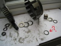
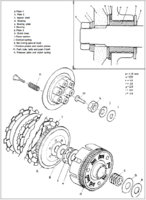
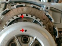
I am about to re-assemble my clutch on my 1979 XS-SF. TwoMany has warned me to be careful of the washer/bearing/spacer stacking sequence so I been reading through some threads and there are a great number of posts about the clutch warning of inaccurate schematics and manuals (not showing parts that should be there). I wonder if anyone can point me to the CORRECT SCHEMATIC DIAGRAM.

I have been trying to trace the cause of the inability to select neutral. All the clutch mechanisms (worm gear, push rods, clutch cable) have now been cleaned, lubricated and adjusted - perhaps my clutch plates I've just taken out had something to do with it (they measured just 2mm).

ANLAF
 
there is extensive information on the clutch in the Tech section have you read that yet ?:wink2:
 
This is the best one I've got / seen...

faf59a260cd73e04e00ad63d7eeeb343_zps4e82c63a.jpg
 
Thanks Peanut, I have been reading the discussions and found all kinds of useful information, and I am still looking.

Watch out for the video-clip I just uploading a video-clip to YouTube, which might take a while to download (it says 110 minutes), so you might have a look at:

YouTube at

It shows the stacking sequence of the washers, spacers, bearings as I removed them, but I am not convinced that it is correct - and there are some random smaller washers in there. I think the previous owner might have worked on the clutch.

The schematic diagrams I have seen in the threads don't seem to match up entirely with the stacking sequence of my spacers, washers, bearings as I removed them. Also, the diagrams don't seem to differentiate (for identification purposes) between the size of the washers and spacers.

Anlaf
 
Thanks, 650Bobber, I have seen this one, and it seems the best one to go with. My washers and spacers don't match up with this stacking sequence entirely - for instance, I have a couple of random smaller washers in there.

My video-clip on (still downloading as I write) shows what I mean.

YouTube at

Anlaf
 
I have attached a photo of my stacking sequence ready to be re-assembled - but what about the random washer? It came off with the other simialr-sized washer at the rear of the assembly (far right in the photo). Help! anyone any ideas before I put it together?

Anlaf
 

Attachments

  • Anlaf's clutch assembly stacking sequence.jpg
    Anlaf's clutch assembly stacking sequence.jpg
    177.9 KB · Views: 870
Yeah I've pulled a few motors down now and there's around 3 different setups I've seen but the differences I've seen are all in I, J, in the pic I posted.. A, B, E, F, G, have all been the same and as per the thicknesses listed in the pic....

The differences I've seen in I and J is the thickness of I and J in some motors is a spring washer and some are a conical washer... But I don't think I and J really matter as long as you have a washer and some sort of sprung washer your good to go.. The main thing is the setup behind the housing and behind the boss....

Haven't had an issues yet setting it up this way....
 
That pic looks right !! it's hard to tell but I think you may have to swap the ? One with the last one...

I've got a setup I can pull down tomorrow to double check and take pix of if you like...
Just let us know...
 
Well, my friend 650Bobber, I think of got them in order now. Only one thing missing and that is the conical spring washer under the nut - but as you say, the main thing is the sequence from there. I'll get some kind of spring washer for the nut then I will put it together.

Anlaf
 
IMPORTANT - I have spotted the stacking sequence on the video misses out the important 'BEARING PLATE e' shown on the schematic 650Bobber sent me. Looks like the previous owner followed an earlier schematic - one of those that left out bearing plate e.

Well, I am learning as I am going along. Thanks for the help. Let me know if you spot anything else.

Anlaf
 

Attachments

  • CLUTCH RE-ASSEMBLY SCHEMATIC.jpg
    CLUTCH RE-ASSEMBLY SCHEMATIC.jpg
    283.4 KB · Views: 1,367
Last edited:
Yeah some of the earlier diagrams show E an F as one unit... That's why I like the diagram I listed....

The order in the vid is defiantly all wrong !! The order in your pic above is the way to go..

In the pic you listed above, does the washer in from the nut say "out" or "out side" on one side of it ? If it does then this is the conical washer and the writing faces you when placed on the shaft... it's a concaved washer that flattens out when the nut is done up... This provides the "spring".
 
Yes, 650Bobber, and I have now followed the schematic you sent me. The washer (nut section) is not the conical spring washer (that is missing), but the plain letter ' 2.6mm. I have just picked up an ordinary steel spring washer - it fits! It was the only one of the correct diameter - its a substantial 4mm.

NOTE - I read somewhere that the clutch basket has to be lined-up with a marker. I can't find that post or thread. Any ideas?

Anlaf
 
BELAY THAT! - I have just spotted the photo posted by RetiredGentleman re the clutch index marks - the marks have to be aligned when putting it all back together.

Anlaf
 

Attachments

  • Clutch Index Set.jpg
    Clutch Index Set.jpg
    33 KB · Views: 1,590
Several methods of locking the clutch hub nut down were employed over the years. The early bikes just used a plain old split ring lock washer. Mid production years changed to that conical or "Belleville" type washer .....

http://en.wikipedia.org/wiki/Belleville_washer

Later years had the set-up you found, a tin locking plate similar to that used to lock the countershaft sprocket nut down. The small tab or tabs bend in and fit into a hole on the hub. This anchors the plate and keeps it from turning. The large tab gets bent up against a side of the nut once it's tight. You have the sequence wrong in your pic. The plain flat washer goes on 1st, then the tin lock plate, then the nut.

Here's a clearer, color-coded washer sequence illustration from that German manual .....

wfEBron.jpg
 
Last edited:
Yeah I've never used the tin locking plate.. I've always replaced with new I an J from my local Yamaha dealer..

Good pic above too. seen it somewhere before but didn't save it.. Did this time tho !!
 
That's brilliant, 5Twins, and I have taken the nut off (not torqued yet) and put the washers in the correct order. You might have seen (above) I bought a spring washer, but it is too thick (4mm plus) and won't allow the nut to bite, so no Belleville or similar.

NOTE - as I polished-up the plain steel clutch plates I noticed they are completely flat on one side and the noses slightly bevelled on the other. I wonder if this indicates they have to face either all bevelled-nose side inwards to the engine or all facing out?

Anlaf
 
The steel plates are stamped out so one side comes out rounded, the other sharp edged. There is no mention of a certain way to install them in any manual I've seen. I like to install them with the rounded edges facing out. My thinking here is that maybe the plates will separate easier when the spring pressure is removed (clutch lever pulled in). If the sharp edges were faced out, they may hang or catch more readily in the hub grooves. I figure the 6 clutch springs will overcome any tendency for the sharp edges of the plates to stick when releasing the lever and pushing them in.

Something some do and I may try next time I have the clutch apart is to round off the sharp edges on the teeth. I haven't done so previously because as devoted to my bike as I might be, I wasn't about to sit there and hand file those bazillion little teeth, lol. But, I think I've figured out another, easy way to do it - a knotted wire brush in a 4 1/2" grinder. That should knock those sharp edges off easily and quickly.
 
That's brilliant, 5Twins, and I have taken the nut off (not torqued yet) and put the washers in the correct order. You might have seen (above) I bought a spring washer, but it is too thick (4mm plus) and won't allow the nut to bite, so no Belleville or similar.

NOTE - as I polished-up the plain steel clutch plates I noticed they are completely flat on one side and the noses slightly bevelled on the other. I wonder if this indicates they have to face either all bevelled-nose side inwards to the engine or all facing out?

Anlaf

You don't want to polish the steel plates. That could decrease the gripping ability. Actually some of the lads have been known to roughen the plates, by rubbing them on contrete, or other abrasive surfaces.
 
That's good to know my friend, RetiredGentleman - and just in time. The job is held up until I can pick up an adaptor for my torque wrench - 3/4 inch socket on a 1/2 inch torque wrench.

I had found some gouging, and I had read somewhere in the threads to rub with sandpaper, which can bring the metal up to a polish. I'll roughen them up a bit as you suggest before I torque it down tomorrow.

By the way, I thought I had messed up when I saw one of the plates left in there, but it wasn't left in there, it is supposed to be there (a base plate, perhaps) and it is held in place by a thin metal tie that goes all around the cogs of the inner basket - phew! Having thought about it, of course there would have to be a base plate in there for the first of the friction plates.

Anlaf
 
OK, it appears you have the later 6 (friction) plate clutch. I thought they started in 1980 but maybe some '79 models had them. It's also possible someone swapped it in as they will retrofit into the older motors (I put one in my '78). That bottom steel plate is dampened, sort of spring-loaded with a very large diameter (same as the plate) Belleville style washer under it. I feel this is the best of the 650 clutches. It engages smoother when taking off in first and the dampened engagement is easier on those little coil springs on the back of the main hub.

Something you may want to check is the steel plate thickness. That one retained at the bottom of the hub is supposed to be a little different than the other 5 in the clutch pack. The manuals state the bottom plate is 1.6mm, the other 5 1.4mm thick. If someone had yours all apart, it would be easy to mix them up as they all look the same.

Now, I'm going to add a little "twist" to the story here. I've never measured the steels in one of these 6 platers. However, when looking at the assembled clutch on a bike I'm working on now, 2 of the friction plates in the stack appear closer together than the others, like the steel plate between them is thinner. I haven't pulled it apart yet and measured the plate thicknesses but if I do find a bunch of 1.6's in there and only one 1.4 (wrongly placed between frictions instead of at the bottom), we may have uncovered another error in the manuals that has gone undetected and uncorrected for years. If you measure your steels now, you could "beat me to the punch" here, so to speak.
 
Back
Top