Crankshaft Taper?

minor crypt opening.
It had been bothering me that I had dad's vernier protractor (somewhere) this seemed like a good excuse to find it.. So after a bit of digging I cleaned it up, set up the crank on the lath and measured again. One thing I had missed; that calculator I had found showed decimal degrees, 2M was talking in degree minutes, the protractor is also marked in minutes.
The set up tool post aligned to the side of the chuck
DSCN3616.JPG

this is the number I came up with
DSCN3614.JPG
DSCN3613.JPG
5 degrees 30-35 minutes. or 5.5 to 5.58 degrees in decimal.
Even with a magnifying glass, reading that was tough.
Yeah long sleeves, but I didn't power on the lathe. 45 in the shop, MUCH warmer than outside.
Like I ever should have doubted 2M "Then I came across some old references to accessory and pulley tapers,calling out an old standard of 3:16.
That's 3/16" per inch, or 2.25" per foot.
Which works out to 10.76° included angle, 5.38° tooling angle.
It's so close that I'd hang my hat on it..."
 

Attachments

  • DSCN3615.JPG
    DSCN3615.JPG
    152.5 KB · Views: 135
Last edited:
I screwed-up earlier.

The 3:16 taper would be 10°43' included angle, 5°21' tooling angle.
The 3:16 taper would be 10.71° included angle, 5.36° tooling angle.

The 1:5 taper would be 11°25' included angle, 5°43' tooling angle.
The 1:5 taper would be 11.42° included angle, 5.71° tooling angle.

...5 degrees 30-35 minutes. or 5.5 to 5.58 degrees in decimal...

That's somewhere in the middle of the 3:16 and 1:5.

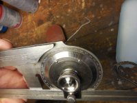
(If I could fit the flywheel on my tiny lathe)
The way I'd try to get the taper would be to,
Use a DTI on the QCTP,
QCTP_indicator.jpg

Use a dial carriage stop.
LatheCarriageStop02.jpg

Chuck-up the flywheel, dial-in no runout, no wobble.
At the fat end of the taper,
- Set the dial stop at the carriage, with at least 1.000" compression.
- Zero the DTI and crossfeed at the large diameter.
- Move the carriage right by 1.000".
- Feed-in the crossfeed, until the DTI is zeroed.
The crossfeed dial will show the radial difference between the small and fat end.
(With the carriage travel of 1.000", we avoid complicated math.)
Take that radial value, and get the arctan, which will be the tooling angle.
Double that to get the included angle.

Ex: Crossfeed difference of 0.100",
Arctan of 0.100 = 5.71°,
Double 5.71° = 11.42°.
 
Last edited:
I did true the crank. I have a tool holder for the QCTP dedicated to a dial indicator, trued to about .0005". Just out of cussedness I may set everything up again. I don't have a carriage stop but see the need.... Being such a hacker it's a good excuse to work on my familiarity with the lathe. Bonus I'm not making scrap metal doing this.
But snow coming, lost fuel prime on the diesel skid steer, fun in the cold for me today.
Edit; victory on the skidsteer, let it snow!
 
Last edited:
That's a terrifying thought.

Yeah, having some sort of carriage stop, indicator, DRO scale would be critical for measuring this taper. Thinking further, if you could get the crossfeed (radial) measurements across a 1.000" carriage travel, then:

A crossfeed difference of 0.100" would be the 1:5 taper.
A crossfeed difference of 0.094" would be the 3:16 taper.
Note that's only a 0.006" difference.

Splitting hairs here...
 
Like Gary said... better lucky. Just going by the "older than me" tool slide scale, I damn near gotta use a puller to get it off the taper. I'll take it. :D
100.jpg
 
My first attempt at an internal taper of 5.4 degrees was a miserable failure, did not measure correctly and it ended up too big. Will have another go soon.
I thought it might be the angle as well but Jims post above confirms that 5.4 degrees will suit my purposes.
 
Back
Top