Dead rotor - best options to fix / replace?

So, investigating the brush forces and pressures, and researching commutator and slipring brush design engineering data.
GASP!! PamcoPete, you're right, this is a world unto itself.

Smoke's coming outta my ears. My head hurts.

I'll save you the excruciating mumbo-jumbo, and try to summarize.

The XS650 brushes measure 5mm x 4.5mm* (.195" x .175") in thickness/width, which makes a brush contact area of 0.225 sq-cm.
The resultant brush to slipring pressures of both new and old brushes comes out to:

NEW (370 grams-force) => 161.2 Kpa (23.4 Psi)
OLD (207 grams-force) => 90.2 Kpa (13.1 Psi)

The recommended brush pressures for a slipring applications are 17.5 Kpa to 20.0 Kpa (2.5 Psi to 2.9 Psi).
This closely matches the pressures listed on your linked .PDF file.

The upper limit for brush pressures is 225 Kpa (32.7 Psi). (cautioned, for extreme applications)
The brush performance tables I viewed don't even go past 75 Kpa (10.9 Psi).

Our XS650 spring pressures are almost 10 times higher than recommended.
The factory probably did this accomodate the XS's harsh vibrating environment and potential rotor irregularities, but this increases brush wear.

If the spring forces were to be relaxed to the recommended levels (about 40 - 46 grams), then vibration, surface irregularities, and rotor runout would definitely be a concern.

Kinda sounds like a 'Harley' solution is used here.
(If it breaks, make it bigger...)
 
TwoManyXS1Bs,

I saw where some very sophisticated brush holders are designed to maintain a constant pressure on the brush even as the brush wears down, so that tells us that spring pressure is important. The wear of the brush is a combination of mechanical and electrical transfer of carbon molecules from the brush to the slip ring.
 
TwoManyXS1bs,

Can I guess that being as you are in Texas, that you worked for NASA at some point? The next thing to investigate is whether the change in pressure on the brush causes a buildup of carbon in the valleys and a cleaner slip ring segment in the peaks. This would result in a higher resistance in the valleys which would in turn reduce the average attainable current in the rotor windings and a subsequent lowering of output voltage.

Hahaha, dear ol' dad warned me about NASA. He knew one of their nose-cone designers, and when the design was finalized and the problem solved, their services were no longer needed. His career advise: "Avoid specialization".

One of the documents I trudged thru discussed slipring surface quality and the other arcane art of reading and grading slipring 'patina'. There's even a sophisticated grading criteria for this 'patina', enuff to make it a career path. This thin carbon layer is actually a desired component of the brush/ring interface. A proper 'patina' will improve conduction and reduce wear. Irregular patina patterns that may develop as a result of slipring runout, and their effects on brush/ring conduction weren't specifically addressed in the data I was reading. I suppose it could be in some patina grading documents.

For our sliprings, it's recommended that the initial surface roughness be around 1 micron, 40-50 microinches. Highly polished (mirror finish) is a no-no. This surface roughness is required so that the brush will initially abrade and create that desired carbon track 'patina'.

I saw the surface irregularity and runout limit of 0.001" in that PDF, and I agree. I don't like any kinds of runout just because.
 
I suppose we could analyse a runout scenario.

Example: 0.020" runout, 6000 rpm, new brushes at 0.5 grams.
This works out to G forces of +/- 10 G's, +/- 5 grams-force
This will produce a pressure variance of +/- 2.3 Kpa (4.6 Kpa total)
This is a significant variance in the ideal 17.5 - 20.0 recommendation.
It's small in our over-springed 90 - 160 Kpa rotor brushes.

Of course, this assumes a vibrationless, frictionless environment.
I'm sure it's worse in the real world.

Another item of note is the brush/ring conduction 'K' factor. The tables don't go out as far as our highly loaded brushes, but it looks like the typical 1.0 ohm brush/ring resistance would go down to about half, 0.5 ohm. And that could be a good thing, given the rotor's low relative resistance. I suppose a rotor/brush/ring conduction experiment is in order.

gggGary's finding runout in just about all his rotors. I'm sure that most rotors out there have some form of unnerving runout. If I found runout in mine, I couldn't sleep at night.

I wonder what the guys at Racetech think about this?
 
Brushes may seem primative in some respects, but they provide a very important service to the average electrical consumer, which is all of us. All large industrial alternators use brushes to supply the current to the rotor, same as our stock XS alternators do.

An electromagnetic rotor gives the utility company the ability to balance out the inductive loads that industry has. Extra current is fed into the rotor to produce a leading power factor, which cancels out the industrial lagging power factor. This helps the utility maintain the correct voltage level to its customers.
 
TwoManyXS1bs,

Well, if you really want to have nightmares, start thinking about brush tilt! :yikes:

tilt.jpg


This is also covered in one of those Googled articles. This is why we sometimes get reports of people who have changed their brushes but they actually experience a lower voltage output! :wtf: You have to wait for the brush to wear in so it is making a better cross sectional contact with the slip ring. This is also why it is important to re install your brushes with the same orientation. :thumbsup:

So, if you are going to start measuring rotor resistance from the brushes, then it's important to slightly rotate the rotor in the correct direction to seat the brushes. You can also see the effect of rotor run out with an ohmmeter across the brushes (disconnected, or course) by turning the engine over with the starter.
 
Pete, yeah, I hear ya on the brush tilt, and break-in. The recomended limits for brush/ring current density are about 70-90 amps per sq-inch, 10 amps per sq-cm. Our brush contact area (max of. 225 sq-cm) is expected to handle about 2.5 amps at full charge rate, which works out to about 11 amps per sq-cm, slightly above recommendation. If the brush is new, or installed backwards, this current density skyrockets. I can see charging issues with this.

The brush experiment I was thinking about would be done on a running engine, ammeter measuring full and partial current into brush feedline, voltmeter measuring total drop across brush/rotor/brush. Knowing the rotor resistance, this could yield the effective brush/slipring resistance. I'd probably just unplug the regulator, and tap into the harness connector, easy 'nuff I guess.

BTW, love your 337 pic! Had a chance at a bargain 336 in '90, but rear IO-360 needed full overhaul.
At $36,000 (for the engine) I let it go...
 
TwoMaNYxs1BS,

Oh...My...God...A Skymaster driver? :wtf: Aren't many of us left.:thumbsup:..Yes, I know the pain. I had two rear engine failures in my 20 years of driving Skymasters, both were maintenance related. I began to think that the mechanics thought I had two engines, so it didn't really matter if one of them failed! Got to the point that I would practice engine out routines with a feathered engine. Didn't climb worth a s%#@ on the front engine, but was OK on the rear. Had a couple incidents where some loose parts from the rear engine exited and hit the prop. Started to think about what would happen if those parts hit the booms. The scariest was when the rear exhaust pipe came apart and hit the prop, both blades. Sold it in 2004. Riding motorcycles now. Much safer. :bike:

Here it is again:

skymaster2.jpg


For those of you that are unfamiliar with the 337 Skymaster, watch the movie Bat*21 with Danny Glover and Gene Hackman. The military version of the 337 was the O-2A.
 
Last edited:
So apparently Yamaha said the heck with brush life; better put some strong springs in to keep it charging "for a while" in a potentially ugly environment!
Doesn't take much imagining to guess that a big ole weight hung off the end of a shaker like the XS crank might have some wobble no matter what it looks like static. Just bearing tolerance and crank flex is going to create "runout".
Yes e-start speed is up at the limit of what you want to do to a gauge!

Should do a side by side, spark plugs in vs. out to see what even compression at cranking speed does to runout....

Push me pull you, looked at those a few times but I never had a budget that could feed a twin.........
 
Yeah, the MixMaster is an expensive rig, especially the 337 retractable version. But it's no slouch, either. I found a Grumman instead. Put 850 hours on it for the same money that would've gone into that rear engine. And I know about throwin' parts. Threw one spinner, almost threw two more. Friend of mine threw a spinner that went clean thru his Mooney's wing. That's a white knuckle ride, for shure.

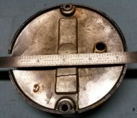
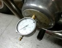
Came up with a gauge mount method for measuring runout on my XS1B. Used an old cover that was centerpunched by a drunk Sportster driver's footpeg. (gotta stop riding alongside weaving riders!!!) For anybody who wants to make one, drill a 1/2" hole, 1.35" from the center of the cover. Tap it 1/4" NPT, and fit a short brass nipple. 1/4" NPT brass pipe is 3/8" ID, and the stem of most dial gauges will slip right in. This is similar to my clutch worm depth gauge tool.
GaugeMount.jpg


I pulled the plugs and gently used the kickstart. Got 0.004" of runout!
RotorRunout.jpg


Now, I've had this bike for 20 years. As far as I can tell, it's never been apart, and there's no sign that the rotor has ever been pulled. I replaced the brushes long ago, and from the brush picture in one of the previous posts, the brushes have worn down only about 1/8". The charging system works fine for me, so I would say that 0.004" runout at least qualifies as a 'tolerable' runout.
 
That first 337 met a tragic end when it was damaged by hurricane Hugo way back in 1989. All the aircraft that were just tied down survived. All of the aircraft that were "safely' in the "T" hangers were damaged or destroyed when the roof collapsed.

1989.jpg

1989-2.jpg


I sold it to the insurance company. Some guy from Florida bought it and flew it as is back to Florida. The ailerons were not synced and they did not have full travel. One flap was drooping down. The spar was bent in one of the wings, but this guy showed up one day, fired her up and flew away. We watched him take off and he had a time keeping her straight, but off he went, crabbing all the way. A few years later I was back in the market for another 337 and I ran the serial number in the FAA registry. The damn plane had been completely repaired and was flying commercially down in Florida!

I bought the second 337 out in Big Bear Lake, CA and flew it back. The rear engine oil filter adapter came loose over Greenville, MS and all the oil blew out of the rear engine, but I was directly over the Greenville, MS airport and caught the zero oil pressure in time to shut down the engine without any damage and landed uneventfully at the airport. The seller paid for the unscheduled landing and repairs. That same thing happened again a while later at one of those high priced airports that only had an official Beachcraft dealership. I was still on the ground and noticed a pool of oil under the rear engine and just knew what it was. The filter adapter was loose but hadn't exited yet, so I had the line person put two extra quarts of oil in the engine and took off headed back home to avoid the $500 that it would have cost to fix the problem. The next day I removed the entire oil filter adapter and installed the factory screen. The PO had already done that to the front engine.
 
Last edited:
Pete. Now, can you explain what happened to your 'N' number? It was reassigned to a Warrier in 2006!!!

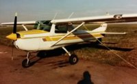
My first bird was a 1969 Cessna-150j. They call those 'timebuilders'.
Cessna-150j.jpg


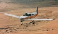
Traded it for a `76 Grumman-American AA5A Cheetah.
Slippery bird. Champion of the 'ground effect'.
AA5A-Grumman-Airborne.jpg


Plenty of cargo space for tent, bags, chairs, table, bicycle, groceries, ...etc.
Great for camping out at Oshkosh!
AA5A-Grumman-Camping.jpg
 
My N number on the first 337 was N337PM. It was a vanity number. The second one was from the factory, N72113. That first photo is not my airplane. That's a file photo.

We are so far inland that nobody thought Hugo would get this far. A few people actually flew their planes in from the coast to our "safe harbor". One owner just had some expensive work done on his Aerostar in Tennessee and flew it back here two days before Hugo. The plane was destroyed. The entire roof of one of the fully enclosed hanger was lifted up and carried a 1/4 mile away, intact! The aircraft in that hanger were not tied down, so they were all destroyed or seriously damaged.
 
Last edited:
Many a good mechanic has complained about 336/337 access for maintaining the engine, and many a poor mechanic has short cut processes just because this or that is a pain to get to. Us guys that have been doing it for a while on the same airframe over and over are well aware of what sucks to do correctly, and what some will do to avoid it. Always liked the look of the 336/337 planes, but never enjoyed working on them. I'll stick to jets for the rest of my days if I can help it, although pretty much everything on a Hawker or Citation 650 is a pain in the ass to do!
 
jd720,

Well, the later models of the 337 like the ones I had had a hatch in the rear firewall to access the rear engine accessories. You could literally change the alternator and both mags while in flight. The side covers on the rear cowl provided very good access as well.

The front engine compartment was a little cramped and the official maintenance manual didn't help much. The factory recommended way to change the alternator was to unbolt all the motor mounts and move the engine forward to gain clearance between the alternator and the firewall, but I found it easier to remove the torque rod for the cowl flaps, which was actually what was blocking the alternator. The factory method took 6 hours. My method took 2 hours.

The really pesky repairs were electrical, and there was a lot of electrical stuff on the aircraft, including cowl flap motors, flap motor, elector trim motors, auxiliary fuel pumps etc. Most of the motors were controlled by micro switches with real Rube Goldburg setups. But, again, the factory recommended repair procedures were just terrible and I think that is where the plane got its reputation for being hard to work on.
 
Hey all, thanks for the tons of input and interesting OT posts too.

TwoMany, its great that someone would be bothered to actually measure a fairly obscure parameter like rotor runout on stock parts and even make up some gear to do the test. My hat's off to you, sir!

A couple of points to make... most importantly, I think my bike /may/ have developed a problem with the engine / gearbox output shaft bearing/s (or something similar) since I did this work. Just a warning flag for now then... if in doubt use a proper impact wrench rather than working against the drive train. I have noticed a few odd noises when the bike is coming to a halt (eg at the lights), the noises disappear completely when stationary but with the engine still idling. Hard to describe the noise, but it's a clunky rattle, and I would guess ominously consistent with a shot bearing. Need to investigate further of course.

Does anyone know, if I have somehow damaged the bearings for the drive (small sprocket) shaft, how much trouble is it going to be to replace them? Engine out job? Can you get to that or those bearings without completely disassembling the whole engine?

RG, thanks for the comments re: charging voltage. I only did a very quick test to make sure it was charging so the 13.8 mentioned was not definitive and was only after 10 seconds or so at around 2000-3000 rpm. I'm pretty sure it is now charging ;'normally' - but to be sure, next time I fire it up on the drive I will measure the charging performance properly. Suffice to say for now that after several days riding with all-lights on, I measured the battery one morning before touching anything else and found the battery at almost 13V, seems just fine.
 
Sprocket nuts are notorious for 'getting loose" even with the washer bent to capture it. Often the inner teeth on that washer are the problem, if they aren't engaged in the shaft slots they keep the nut from tightening properly. If that's the problem it usually leaks a bunch of oil too.
 
Back
Top