-
Enjoy XS650.com? Consider making a donation to help support the site.
XS650.com receives a small share of sales from some links on this page, but direct donations have a much greater impact on keeping this site going.
You are using an out of date browser. It may not display this or other websites correctly.
You should upgrade or use an alternative browser.
You should upgrade or use an alternative browser.
Digital Gear Indicator for the XS650
- Thread starter TwoManyXS1Bs
- Start date
Haahahaah, Resto. That is absolutely hilarious!
Fell outta my chair...
This is the debounce circuit schematic for the DownShift signal.
It uses the +5v power and ground as supplied on the gear indicator board.

This is the debounce circuit schematic for the UpShift signal.
It also uses the +5v power and ground as supplied on the gear indicator board.

The two debounce circuits are identical, except for the redirected ground for the final NPN transistor of the UpShift circuit. That connection goes to the microprocessor's pin #14, which is the drive signal for "Segment b".
Edit: A note about this debounce circuit. The 1meg resistor and 100nf cap (0.1 uF) create a signal debounce of about 100ms (0.1 sec). Once a 'grounded' signal is detected, the circuit 'traps', ignoring any additional spurious signals, and will continue to ignore until at least 100ms of clean 'open' signal is achieved. That'll get rid of the gliches. And, nobody can shift fast enuff to fool it into a false shift...
Fell outta my chair...
This is the debounce circuit schematic for the DownShift signal.
It uses the +5v power and ground as supplied on the gear indicator board.
This is the debounce circuit schematic for the UpShift signal.
It also uses the +5v power and ground as supplied on the gear indicator board.
The two debounce circuits are identical, except for the redirected ground for the final NPN transistor of the UpShift circuit. That connection goes to the microprocessor's pin #14, which is the drive signal for "Segment b".
Edit: A note about this debounce circuit. The 1meg resistor and 100nf cap (0.1 uF) create a signal debounce of about 100ms (0.1 sec). Once a 'grounded' signal is detected, the circuit 'traps', ignoring any additional spurious signals, and will continue to ignore until at least 100ms of clean 'open' signal is achieved. That'll get rid of the gliches. And, nobody can shift fast enuff to fool it into a false shift...
Last edited:
It's up to ya'll how you'd like to layout the debounce circuitry. I managed to squeeze both circuits onto a small paddle-board, small enuff to squeeze back into the original unit's box with the processor board.

This shows the connect points on the processor board.

Run little jumpers from those connection points to the paddle board.
Use appropriate lengths so that the paddle board can be folded down atop the processor board. This is only if you want to be able to fit the whole shebang back into the original box.

Use appropriate lengths so that the paddle board can be folded down atop the processor board. This is only if you want to be able to fit the whole shebang back into the original box.
Testing the thing. Individually grounding either of the UpShift or DownShift wires produces a clean, singular number change, from 1 to 5, back down, all combinations in between, and never goes above "5". The "neutral" wire, when grounded, always produces a "0", and resets the unit.

Sandwich a strip of electrical tape between the two boards, jam the mess back into the box, and wrap it up.

This is now a 5-wire system.
Red - (+12v) switched ignition
Blk - Ground
Grn/Wht - UpShift sensor
Grn/Blk - DownShift sensor
Wht - Neutral
This is now a 5-wire system.
Red - (+12v) switched ignition
Blk - Ground
Grn/Wht - UpShift sensor
Grn/Blk - DownShift sensor
Wht - Neutral
This is as far as I've gotten. Working on the shift sensor thing now.
Well, when it's warm enuff out there...
Well, when it's warm enuff out there...
2M, you have been very busy! I like the self centering switch idea and the debounce circuitry. My question relates to the diodes D4 and D7 which sit on the inputs. What is their function? Do they just sit there to provide a logic 0 of about 0.6 Volts (rather than a true 0 Volts if they were not there) for stability reasons? And that neutral wire, is it a reset to O (neutral) using the neutral switch just in case the display numbers get out of sync?
Thank you.
Edit: Just saw the explanation of the neutral wire.
Thank you.
Edit: Just saw the explanation of the neutral wire.
Last edited:
Holy cow 2M - this is truly excellent work!
I freely admit that even though I have made a 36+ year career working at the pointy end of advanced engineering (mechanical engineering) such as metal fatigue, vibrations and stress analysis and hydraulic power, I have always found electronics to be.....mystifying. I know how to solder competently, but actually designing a circuit is beyond me.
I am really looking forward to seeing the full implementation - this is exciting! Its sort of like a window into what would have happen to the XS650 if Yamaha hadn't stopped building them in 1983-85. (I can't seem to find a definitive answer as to when production actually ceased).
Pete
PS - as with the Honda ST Owners forum, there really is a HELL of a lot of talent on this site. I recently received some magnificent XS650 and Yamaha (in Triumph style font) tank and side cover emblems cast in pewter by my countryman Resto - and they are stunners. They'll have a place of pride on my cafe project build.
2M, you have been very busy! I like the self centering switch idea and the debounce circuitry.
Thanx, Paul. I'm hoping that the self-centering switch, its lever actuated by a single notch/groove, will simplify the adjustments.
...My question relates to the diodes D4 and D7 which sit on the inputs. What is their function? Do they just sit there to provide a logic 0 of about 0.6 Volts (rather than a true 0 Volts if they were not there) for stability reasons?
There's 4 inputs to the gadget that have those mini-diodes, those 2 plus 2 more, +12v and neutral. Standard practice with gadgets that interface with the outside world is to have "diode protected inputs". Simply averts potential damage from spurious voltages and "reverse bias" (accidently wiring it backwards, or affixing to positive ground machines). So, they're just protection devices.
Because of their 0.6v forward-voltage-drop, they have to be removed, or bypassed. When I tried the circuit with them left in there, in series, the signal didn't ground enuff to trigger the device.
The debouncer should be able to provide similar protection.
...And that neutral wire, is it a reset to O (neutral) using the neutral switch just in case the display numbers get out of sync?
Thank you.
Edit: Just saw the explanation of the neutral wire.
Yeah, it simply ties into our bikes' neutral wire, triggered by the neutral switch's ground. In neutral, that line grounds, and the gadget displays a "0". No matter the existing gear, the internal counter gets reset, and the next shift change will produce either a "1" or a "2"...
Last edited:
Holy cow 2M - this is truly excellent work!
I freely admit that even though I have made a 36+ year career working at the pointy end of advanced engineering (mechanical engineering) such as metal fatigue, vibrations and stress analysis and hydraulic power, I have always found electronics to be.....mystifying. I know how to solder competently, but actually designing a circuit is beyond me...
Hey, Pete! Thankyew, thankyew. Those accolades mean a lot coming from the experienced professionals. And, yes, electronics can be mystifying, even terrifying to some. I'm hoping that these little circuits will pique the interests of the curious, and budding electronics techs out there.
...I am really looking forward to seeing the full implementation - this is exciting! Its sort of like a window into what would have happen to the XS650 if Yamaha hadn't stopped building them in 1983-85. (I can't seem to find a definitive answer as to when production actually ceased)...
I think the guys here reported that final production was in 1983, with residual stock being sold off as 1984?
The '80s were a tough time for vehicle manufacturers, trying to implement ever-stringent EPA and safety items, using flaky/temperamental emerging electronics. A learning curve for sure, with customers serving as field-trial guinea pigs. Just the safety interlocks on the later XS650s are mind-boggling. More of that stuff could have easily, if not already, sealed the XS650's fate.
...PS - as with the Honda ST Owners forum, there really is a HELL of a lot of talent on this site. I recently received some magnificent XS650 and Yamaha (in Triumph style font) tank and side cover emblems cast in pewter by my countryman Resto - and they are stunners. They'll have a place of pride on my cafe project build.
Absolutely. There's some seriously talented and experienced folks in here. And, yes, Resto's emblems are indeed stunning.
For all the goofing-around I did on my XS1B back in the '70s, what I've learned here on this forum is at least an order of magnitude greater. What a great site...
Took forever to figure the dimensions for this.
Made the little vertical mount for the toggle switch.
Yesterday was definitely a BAD day for welding.

Just call me "Mud dauber".
Everything went wrong. Had trouble getting a good arc. I forgot to clamp ground. Left the clamp resting on the metal table, and the ground current somehow found its way across the table. Then the gun stopped feeding. Ohno, birdsnesting? Pulled on the wire, it easily pulled out of the gun. Now what? Oops, simply ran out of wire. Fumbled about reloading it, dropped the 2 lb spool on things that don't like excitement. Finally reloaded, back at it. *Flash* *Splatter*. Forgot to lower the welding lens, forgot to reset heat and feed. Try again (after the white spots disappear). Now I've got a good arc, but, what's it doing over there? I was a half inch off, and dobbing in the wrong place. Now the auto-dark lens decides to darken just before pulling the trigger, like it has ESP? It's falsing on the reflected lighting from the table. Ok, remove the table and move everything to the floor. Scrunched down, can't hold steady. Well, just glob it in anyway, nobody will see it. *Gads* I'm way out of practice.
Had to use the standard exchange rate of 1 hour's grinding for each 5 seconds welding. Finally got it cleaned up, and did a mock fit of the switch.

At least it's coming together...
Made the little vertical mount for the toggle switch.
Yesterday was definitely a BAD day for welding.
Just call me "Mud dauber".
Everything went wrong. Had trouble getting a good arc. I forgot to clamp ground. Left the clamp resting on the metal table, and the ground current somehow found its way across the table. Then the gun stopped feeding. Ohno, birdsnesting? Pulled on the wire, it easily pulled out of the gun. Now what? Oops, simply ran out of wire. Fumbled about reloading it, dropped the 2 lb spool on things that don't like excitement. Finally reloaded, back at it. *Flash* *Splatter*. Forgot to lower the welding lens, forgot to reset heat and feed. Try again (after the white spots disappear). Now I've got a good arc, but, what's it doing over there? I was a half inch off, and dobbing in the wrong place. Now the auto-dark lens decides to darken just before pulling the trigger, like it has ESP? It's falsing on the reflected lighting from the table. Ok, remove the table and move everything to the floor. Scrunched down, can't hold steady. Well, just glob it in anyway, nobody will see it. *Gads* I'm way out of practice.
Had to use the standard exchange rate of 1 hour's grinding for each 5 seconds welding. Finally got it cleaned up, and did a mock fit of the switch.
At least it's coming together...
Last edited:
Well, you're getting there.....
Following with interest.
Pete
Following with interest.
Pete
I am itching to see that switch mechanism all finished. I have not stopped thinking about this project, very interested! Keep up the good work!!!.
This 'switch mount' was supposed to be a quickee.
I guess a little tractor paint wouldn't hurt.

The switch mount hole, and main mount slot were masked off, for the grounding path...
I guess a little tractor paint wouldn't hurt.
The switch mount hole, and main mount slot were masked off, for the grounding path...
I'm still trying to figure out where this gizmo fits on - can you shoot us a photo of it installed?
Pete
Pete
My 75 GT-380 was always stuck in 8th gear.
uncle meat
XS650 Addict
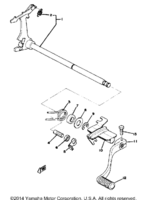
It's the chain guide close to the shift shaft... #10.I'm still trying to figure out where this gizmo fits on - can you shoot us a photo of it installed?
Pete
Attachments
Ahhhhhhh.....NOW I see.
Thanks Unc.
Pete
Thanks Unc.
Pete
Similar threads
- Replies
- 6
- Views
- 475
- Replies
- 19
- Views
- 2K