Flasher blues..

What color should the "75 end up, I will use the factory Decals

  • Stock Black sparkle

    Votes: 6 85.7%
  • Aqua or Sapphire "73TX blue flake

    Votes: 0 0.0%
  • Ruby Red Flake

    Votes: 0 0.0%
  • you name the color.....

    Votes: 1 14.3%

  • Total voters
    7
  • Poll closed .

Orion61

XS650 Addict
Messages
371
Reaction score
119
Points
43
Location
Sioux City Iowa
Hi guys, sorry for taking advantage of your expertise, but when I finally get my old 75 back on the road again next Summer you will all have a partial ownership in her! lol..
I cannot tell you what it means to have a bunch of friends like you that can jump right in and pitch relief for each other.
Here is what I have gotten accomplished so far with your help. Remember the bike has been sitting with bad gas in it since 2002!!! YIKES!
1- Got the carbs boiled out with Pine-Sol, then cleaned with Gumout and air compressor.
2- New Battery/got it running again! So sweet to hear that engine thumping again!
3- Got the spongy handlebar grommets/riser fixed at NO EXPENSE! thanks to you guys!
4 -Just Today WED-9/28/16 replaced the bent clutch and front break levers, flushed out and bled the front caliper. Got my old Dealer OEM seat on replacing the old seat with rips.
5- got the mangled front flasher mounted (still no power to it)....
That brings me to this new Thread I need some help with tracking down the wires for the front Right flasher.
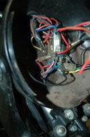
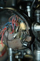
The rear Right one USED to come on but not flash, I have pictures of the Headlight pan. Someone (not me) at some time in the past has soldered two wires and left them cut and ready for?????
If anybody knows what the wire they are soldered to is for, I realize I don't have a ground wire on the flasher.
I can take a multi-meter with me next time, so to start this off please remember I know nothing about the electrical systems on these and I might as well be trying to read Chinese if you have me look at schematics...
Here are the pics, please excuse the mess, it is just an emergency work space in an unused building filled with JUNK.... Think of this as a refurbishing project, still have the forks to put new seals in, I would love to trade the stock forks for a 4" over set. I also have the bushings and new rod for the swing arms..
When everything with my messed up disability gets paid I might even have enough for new decals and a paint job.. I am thinking of the stock decals and Aqua flake, or the 73'TX color which I have always loved!!!
solderedred.jpg
solderedred.jpg

Does anybody else have an opinion for a color for "our bike" since you guys have helped me so much..solderedred.jpg DSC_8859.jpg DSC_8856.jpg DSC_8857.jpg DSC_8858.jpg solderedred.jpg DSC_8859.jpg DSC_8856.jpg DSC_8857.jpg DSC_8858.jpg
 
Your pointing at something.....why? Indont think there are any solid red wires on these bikes.
 
"Your pointing at something.....why? Indont think there are any solid red wires on these bikes" I am not pointing at something, just holding the wires back to give you a better look at the wiring..
I am trying to get my Right Flashers to work. I am asking if anybody knows what the wire the 2 solid red wires are soldered to is for?
I am going to get rid of the added wires if they aren't supposed to be there.
The other pictures are there to show the things I have done to the bike. WHY? Because there is another member that asks for help and either ignores the advise
or does something different, or nothing at all!
I forgot to ask, is there 2 flashers or just one that handles both sides? There were an ugly after market set of flashers mounted on the handle bars. They were so ugly I took them off and put stock flashers on. the Left side worked fine, the right side had the rear working but not flashing. The FRONT Right flasher has never worked.. I know I don't have a ground wire on it, but I don't know which wire the ground should go to?
I have never worked on the electrical system, but I have seen what a mess people have made out of other bikes!
thanks for the help..
Larry
 
Hi Orion,
there's ONE flasher unit. The left/right switch button tells the pulsed power which side to flash.
Stock Yamaha wiring has Green wire to the righthand signals and Brown wire to the lefthand signals.
Gawd knows what colors the dreaded PO swapped in.
FWIW, the wires going into the middle of the signal stalks are the power feed wires, yours are both colored Black (or perhaps Dark Brown) rather than the stock Brown & Green but that don't really matter so long as you know about it.
Look for wires that come from the signal switch and go hot when the switch is turned.
There should be one wire for each signal coming from the switch and each should have a 1 into 2 connection inside the headlight shell.
Each 2-way feeds one front signal and one rear signal.
What I DON'T see in any of your photos is a rightside signal ground connection.
It should be a ring-connector that fits over the signal's threaded stalk and is trapped under the signal retaining nut. Looks to be one on the leftside signal though.
The ring connector should be crimped or soldered onto a Black ground wire which should test out to be good right back to the battery.
If your rear signals ain't been messed with, they should be grounded that way too so best check there also.
Oh my, that's a lot of "should be's" and you'll need to check every last one of them.
 
Last edited:
Thanks guys The 2 previous answers are EXACTLY what I was looking for! I knew there was a ground strap missing. as I JUST put the flasher stalk on it and the old wire was missing. I can't really read schematics very well but it looks like the right flasher is a dark green wire.
It doesn't look like the Previous owner cut and clipped a lot of things in there just added the two red wires.
My bet is he had a set of running lights hooked up to the crash bar! that makes sense as there were some goofy looking brackets on there when I bought it.
I am betting the guys at the used cycle shop just cut them as you see. The steps you gave me are perfectly clear so I will take my meter up there and see if I have voltage to the flasher.
The best news I could have possibly asked for was answered yesterday as I have a right knee that had been replaced and revised 4 times along with a torn quad and nasty spat with MERSA Staff infection, I was able to kick it over and start it. Even tho the electric starter works it is like most with it kicking out when it wants to. In the 25 years I have owned it I never used the starter, it always started on the first or second kick.
I really feel like I am making huge progress on it, I would never EVER have been able to get all this work done without all the advise you have given me.
you really feel like my Brothers here and I cannot thank you enough!
Larry Beach...
The only "Son-of-A-Beach" you will talk to today
 
I use the same keys as the diagrams for clarity and correct terminology. This is very important for everyone, not just a novice.

Those red wires can be cut from the L, (Blue), wire. That L wire, is the power for the instrument lights and Tail-light. ...........Tail-light Y, (yellow) is power from the brake switch for the Brake light

Ok for the record...............There are different shades of green and brown in the wiring loom. So saying Green, Brown or Blue is going to confuse and put you wrong. Wiring keys are important for identifying the correct wire.

The indicator wire colors are as follows.
Right indicator wire is Dg, (Dark green).
Left indicator wire is Ch, (Chocolate).

These two colored wires are often mistaken for B, (Black), especially on old bikes. It is important to clean all the wires with something like WD40.

The power wire that come out of the indicators are Black and these need to go into the Dg and Ch multi connectors. The connectors from the indicators will be a male bullet type and they go into a triple female connector. The multi connector has a provision for another Dg or Ch male bullet, (coming from the Left hand switch) and a fixed Dg or Ch wire coming from the loom, (rear signals).

This is where wiring diagrams are Chinese for novices, I know because it used to do my head in when i was learning this stuff. I would have to walk away and come back days later some times.

When looking into the bucket from the front, left and right side of the bike is reversed. So what is seen as right is left when sitting on the bike, and vise versa
74 TXA Assembly manual - parts  Manualt17 17 copy 1.jpg
 
Last edited:
Right and left are always as if sitting on the bike. Even when looking into the bucket. Confusing? Yes. But now u know.
 
Yes angus67, But on the diagram i used, (from the 74TXA assembly manual), it shows the left and right lower grommets, (9 and 11), labeled as you see them looking into the bucket, and not left and right as sitting on the bike.........................Yamaha done this just for confusion purposes, lol
 
Last edited:
On your turn signals, in the flasher socket, the brown wire is power in, the brown/white is power out, the black is ground. Your stock flasher maybe bad, building a jumper wire for testing is not hard to do. Plug on end of jumper into the brown wire, other end into the brown /white wire. This will give the switch power. This will light the lights but no flash. If this jumper lights the lights then your flasher is bad, no worry there most any two prong flasher will work.
With the jumper in place turn switch to the right side. I the headlight bucket use your multi-meter on the 20 VDC scale and probe the dark green wire for power. Your dark green wire may appear black, this probing for power will help identify the dark green wire. Once found plug your right turn signal power wire into this wire.
Put the switch to the left position and probe for the chocolate wire, again it may appear black. Once found, plug the left turn wire in.
Once you have found the power wires, plugged in the lights and put the missing ground on the right light you should get the lights to light.
If you get that far using the jumper wire, then it's time to try your stock flasher. The stock flasher needs both the front and rear lights to work and have the 1156 27 watt bulbs and the 3 watt dash indicator bulb to flash. With all the draw the two 27 watt bulbs have the lights may not flash with just battery power. Often the bike has to be running and with enough rpm's to create full power.
Leo
 
That is why I asked if there were one or two flashers, because my Left flashers both work. I should be able to trouble shoot it in the Headlamp bowl. I think I just need to find the Right wire for the Right signal and ground it. When I got the bike there were two hideous flashers mounted to the roll bar that worked. They had homemade mounts that were banged up, and rusty. There were just two bolts in the headlamp bowl.
I took them off and put a stock set of flasher stalks on. The one on it was broken when a sudden storm came up with 97 MPH winds and knocked the bike over!
I just put another good one on, I need to rig up a ground wire for it soldered on a washer. It may be that simple, BUT the rear Right flasher would light up but not flash
when I parked it 12 or 13 years ago. so that may be just a bulb, or the switch may need cleaned.
I am just going through the typical things you need to do when a bike sits untouched for over a decade. I may be able to get in there this afternoon with a multi-meter.
and chase that Dark Green wire down.
 
Left, Ch, and Right, Dg, indicator circuits only have these 2 colors, and the black, (power), from the indicator, going in and out of their separate Multi connector

Had a good look at the bucket and here is what i found

Where the Dg, (dark green), wire goes into a multi connector there is also a R/Y, (Red/Yellow, hard to actually make it out), wire going into the same multi connector. These should not be together
DSC_8856 copy.jpg
The right indicator B, (Black), power wire is going into a multi connector. This connector should be the Dg wire circuit.
solderedred copy.jpg
In this pic above, the connector that appears to have no insulation and the connector where i pointed out the Dg and R/Y are together, need to be sorted out
 
Last edited:
Left, Ch, and Right, Dg, indicator circuits only have these 2 colors, and the black, (power), from the indicator, going in and out of their separate Multi connector

Had a good look at the bucket and here is what i found

Where the Dg, (dark green), wire goes into a multi connector there is also a R/Y, (Red/Yellow, hard to actually make it out), wire going into the same multi connector. These should not be together
View attachment 89234
The right indicator B, (Black), power wire is going into a multi connector. This connector should be the Dg wire circuit.
View attachment 89235
Where should the wire that isn't supposed to be together go? (Looks like a red/yellow? and dark green) I don't believe I put them like that, but who knows. I will insulate the wire connector. Is there a fuse for the Right flasher that connector may have shorted??? and do you know where the fuse is?
Everything else works as it should on the bike.
Skull (everybody else) I dearly appreciate your help in this matter!
Things I have gotten done so far:
Carbs/Tank/Petcocks cleaned. Tank is Kream coated.
New battery, Bike is now running, it still pops when cold a bit, showing there is still SOME partial blockages idle..(like me I have 5 stents) It is running well enough that I believe just RIDING with carb/injector/Seafoam cleaner will resolve.
Mushy handlebars have been fixed and are now secure.
New brake and clutch levers.
Throttle was frozen now cleaned and lubed cables.,
Front Brake has been flushed out refilled and bled.
Broken front right signal replaced.
Seat has been replaced with an old Dealer take off, cover is soft and un-damaged. My old seat isn't that bad, 2 small tears low/front on each side that were repaired 20 years ago and both still holding, no other rips in the seat. Anybody need the old seat?
A new gasket for the cam chain tension-er that is leaking oil (never leaked before)?/ and It used to have a slight leak on the bottom gasket of the Left cyl, not leaking now????
YET TO DO...
Have a new Clutch cable but will wait for now,
Have fork seals and covers,
New Swing arm bushings with bearings, to be put on..
(I have an MP4 of it running if anybody wants to hear it) I just figured how to convert Tape to Digital).
I have a nearly new Suzuki Boulevard with under 6,000 miles on it, but I still prefer the XS, It will be repainted with new Decals.. that is what the POLL questions are for,
 
power comes to the ignition from the Red wire, then power runs through the R/Y wire that runs from the ignition switch to the On/Off headlight switch.

On My TXA, (same as the 75B), the R/Y wire from the ignition is a double connector. A single R/Y wire with a male bullet connector should go into the double connector.

The connector where the Dg and R/Y are together needs to be identified so the correct wires feed into it.

All wires should be joined by color to color. No mix and match with the exception of the Indicator power Black wires to the Ch and Dg

Note: Some double connectors will have one wire running to them. Not all but some.
 
Skull here is one more angle of the bucket, I don't know if it helps you out here...Brother I am going to owe you BIG TIME!
Sorry the other pic focus was off due to the Nikon auto focus.. I don't know if you can get anything new from them..
I may need to just take them apart one by one, and untangle them and clean them each off. I see one bit of Black tape wrapped around
a cluster of wires, that is usually bad news.
I can't tell you how much I hate it when people mess with wiring when they don't have a proper schematic or knowledge, it ALWAYS causes MORE problem than it fixes.
 

Attachments

  • top.jpg
    top.jpg
    152.4 KB · Views: 79
  • DSC_8854.jpg
    DSC_8854.jpg
    127.8 KB · Views: 106
Nothing new. identifying the ones i pointed out and taking pics of them would help.

Yea untangling the wire is the next step. It's not easy but work on one set of wires at a time, meaning, say the right side of the bucket/loom and do one side at a time. It seemed like hours when i done mine, (80SG, a lot more wring), and i found i had to do some wires more than one because i was unplugging/untangling the rejoining then when i went onto another set i sometimes had to redo some i had already done

I continuity tested my wiring as i went, this also helped me to get my head around the actual loom and related it to a diagram. Continuity testing is for resistance only. It will tell you if the wire is damaged or broken or a connection is corroded to the point where it is not allowing full power to get through.

I cleaned every bullet connector, both male and female and the couplings. Used some fine wet/dry sandpaper for the male bullets and my Dremel drill with a small round ball end for the female bullet connectors. That small 6 pin connector is a pain but needs to be taken apart to clean the terminals

Also used a cotton bud with some Lanolin oil on it and inserted it into the female connector to clean it out after the Dremel cleaning.

Lanolin oil is an anti corrosive and wet start, so it's safe on electrical wiring and circuits

Before.................................After
P1000974.JPG P1000980.JPG
 
Last edited:
There should be only one turn signal flasher. As mentioned power goes to the flasher on a brown wire, from the flasher to the turn switch on a brown/white wire. The switch sends the power to one side or the other. One flasher works both sides.
So at this point when you put the turn switch in the right position the rear lights but don't flash and the front don't light. Is this correct?
If so hooking up that missing ground should put things right.
That would be my next step.
Instead of trying to solder a wire to a washer, go the Wal Mart or any Parts store and buy some ring terminals, large enough to go on the threaded stud that holds the turn signal into the bucket. You can also buy bullet connectors there too. Make a wire up, this can also be bought at the same time as the terminals, to match the ground wire on the left side. A ring terminal on one end, a bullet terminal on the other. Install as on the left.
Leo
Hi Leo that is correct, the rear Right flasher turned on but did not flash, but now it is not turning on at all, the bulb may be bad or the contacts, it has been sitting
for 12-13 years. The one good thing I did was to kick it over every year so it didn't lock up. I am hoping to get there later today or tomorrow.
 
Back
Top