lightfall
XS650 Addict
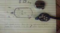
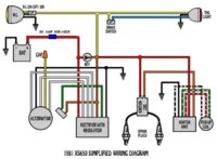
My aftermarket headlight with daytime running bulb needs to be hooked up to my new wiring harness (which is based off of the 81 simplified wiring diagram). The headlight has 5 wires: blue, white, brown, black, green. It seems to me like the blue probably = high, white = low, brown = daytime pos black = daytime ground, but the rest I am not sure about and whether or not I can splice the daytime to the main pos/ground and not overload anything?
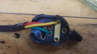
My switch is an Emgo 3 position with 2x momentary switches that I wanted to use as low/off/high and starter and kill switch. This switch only has a black, red, green, yellow wire. There is no manual for this switch and I am lost...if I go black to battery and red to battery then the 3 position works as yellow high and green low but how do I get the starter and kill switch to work?
Any insight?
Headlamp: http://www.dimecitycycles.com/vinta...black-mini-bates-brass-headlight-67-7710.html
switch: http://www.dimecitycycles.com/vinta...ebar-turn-signal-blinker-switch-46-68900.html
Attachments
Last edited: