Help save my trip! Bike doesn't run when warm

I have measured the pick up hot and cold. Values are somewhat high with 850 ohms hot (2x) and 780 cold. Both wires give the same reading.

Before I left I disconnected the tacho when the bike was running weird, it didn't affect it. I checked the wiring in the headlight, it's fine and undamaged.

I got a modern fuseholder, I can try your suggestion with lower A Fuses.

And regarding the exhaust, I understand but this is electrical for sure. We checked the spark last time it died. We didn't see any sparks, but my friend did get zapped. Maybe it is or was sparking super weak.

Let's see what happens today. At least the view is nice
View attachment 175142


OK New INFO

We checked the spark last time it died. We didn't see any sparks, but my friend did get zapped. Maybe it is or was sparking super weak.

I have had problems with Boyer Bransden at times ..I then sometimes draw separate wires outside the wiring loom
from Battery to ignition parts Coil and Ignition Box Ground to minus on battery
At this point in time I still have those extra ground wires there. did not remove them last time.
+ 12 V Positive can not be there permanently because the box dont withstand that
But I feel it is OK for a short while testing . Fuse there is of course good. But I did not have one.
Later on the + 12 V can go via ignition lock .and wiring loom.

When the spark is there please notice if any difference.Right or Left
Boyer is a Waste spark system so one can move the spark plug caps ..between sides
I dont know if Yamahas box is the same.

I this manner ( Extra wires ) one can ensure that the Ignition parts have the right " Physics " IN
Since 2 boxes been there it is not the box most likely.
 
I know what it is 99% sure. Just spoke to the guy at carmo who developed this ignition. Here is the thing:

It's using the pick up for signals. Because it's digital it's better at advancing the curve quickly. Downside is that it's more sensitive to a wrong pulse (long technical story)
Ones the bike heats up it affects the pick up. Just measured the resistance: 940 ohm each. Should be 700 at 20°c. Gonna remeasure when cold.

Just drove with the oem ign. No issues!!!

According to the guy this s because it's hardware is less sensitive to the difference in peaks of the signal.

Plan now: reinstall the oem TCI . It runs but doesn't advance good. So less top speed. But it's a runner!

View attachment 175061
Sounds like CARMO has a design flaw. Because if your bike pick ups are doing it probably most all Yamaha’s are going to heat up and do the same thing.
 
New info, yesterday the bike did good. It didn't die on me. I did get weird new stuff:

When I brake the hi beam indication light comes on. But only when in gear (not in neutral)

When I turn the light on during the ride, they are very dim. When I make more revs, the light dims even more and would even go out.

When low beam is on, the hi beam indication light would shine a little.

Weird right?
xs650.jpg
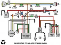
This scheme is pretty close to what I have.

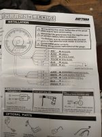
Here is a schematic from the tacho I have. A X Means I don't use the wire. Basically I already had a indication light for hi and neutral with the original dash. I used those for the new tacho.
IMG_20200828_202127522_HDR.jpg
 
New info, yesterday the bike did good. It didn't die on me. I did get weird new stuff:

When I brake the hi beam indication light comes on. But only when in gear (not in neutral)

When I turn the light on during the ride, they are very dim. When I make more revs, the light dims even more and would even go out.

When low beam is on, the hi beam indication light would shine a little.

Weird right?
View attachment 175193
This scheme is pretty close to what I have.

Here is a schematic from the tacho I have. A X Means I don't use the wire. Basically I already had a indication light for hi and neutral with the original dash. I used those for the new tacho.
View attachment 175194


It sounds as if it has been raining on the bike.
According to my Experience problems described latest is in most cases in the Connectors or Switches I know fex Jim have had other Experiences.
On a stock wired bike the handlebar switches left and right would be first.
Since I am more familiar with the stock wiring this is now. An electrical fault finding problem in an Unknown wiring.
On line ..

This scheme is pretty close to what I have.

If it is according to the schematic I would inspect Connectors and Switches and then consider new wires everywhere.
By the looks of it -- it is not that large.
Stock factory wiring has Quality aspects which is Uncertain in a " DIY " wiring.
There can be rust in every connector. And substandard wires with cracked Insulation.Not properly crimped Connectors.
That might work in dry " Desert " states in the USA .But not in Europe rainy summers.
Japanese Quality control was second to none in 70 ies.

The Downsizing of Fuses is a simple way forward perhaps worth trying .But it sounds as a New wiring is needed.
Perhaps I later get time to look at the Schematic but I doubt .Solid -Valid Conclusions can be drawn

( edited was a smiley there by mistake sorry about that )

 
Last edited:
New info, yesterday the bike did good. It didn't die on me. I did get weird new stuff:

When I brake the hi beam indication light comes on. But only when in gear (not in neutral)

When I turn the light on during the ride, they are very dim. When I make more revs, the light dims even more and would even go out.

When low beam is on, the hi beam indication light would shine a little.

Weird right?
View attachment 175193
This scheme is pretty close to what I have.

Here is a schematic from the tacho I have. A X Means I don't use the wire. Basically I already had a indication light for hi and neutral with the original dash. I used those for the new tacho.
View attachment 175194
I'll guess lack of ground wires.
All the DIY wire diagrams leave out the ground connections, but the rubber anti vibration mounts on an XS mean a ground loom is a necessity.
ground wires from battery to frame, engine, fork, headlight bucket, gauges, handlebars, tail light, and turn signals is needed.
 
I did take a Quick look at the Schematic
firstly on it there are only 4 fuses 1 x 20 A and 3 x10 A
On the picture earlier on # 65 it looks as 5 fuses are there all red aka 10 A
That leads to a question what does the extra 10 A do
Furthermore one Brown wire goes to front and rear headlamps
It would be simple to measure the voltage on that brown so it is 12 V
fex at the fuse holder.
And then remove both those 10 A fuses
Riding without lights a bit ( not recommending illegal activities
But as daytime riding for fault finding .. )
Or when misfiring happens or other weird things pull those2 fuses
perhaps one at a time or both at once.
 
I'll guess lack of ground wires.
All the DIY wire diagrams leave out the ground connections, but the rubber anti vibration mounts on an XS mean a ground loom is a necessity.
ground wires from battery to frame, engine, fork, headlight bucket, gauges, handlebars, tail light, and turn signals is needed.

So it's been a few days and I want to continue looking for the gremlins that have been haunting me.

I red back some of the last posts to make sure I didn't miss anything.

I fully understand that helping me out with a custom wiring loom is very hard.

I like to believe I did a thorough job on this wiringloom 2.0. I have worked for truck manufacturers where the fastening of wires with zip ties was an real art. Chafing was a real concern so everyone got trained into how to secure wires on a truck.

Secondly I worked for a company developing electronics for the car industry. Here I performed environment testing on everything, from cables to connectors, enclosures and complete systems. I learned how capillary action can travel for meters through wiring from on end to the other and damage circuit boards. I know how the thermal cycling of circuit boards will eventually cause mechanical failure in the soldering connections of the board. I understand the influence of sinus- and random vibrations. I know a thing about IPC rated soldering and crimping of connectors

Anyway what I'm trying to say here is that I have taken all this info into building the wiringloom. I'm not saying it's perfect. Hel I even plan on making version 3.0 to make stuff easier to troubleshoot. And improve some things. I realize that the xs650 is quite a hard platform for electronics considering vibrations.

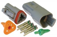
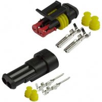
I've replaced the terrible OEM connectors from Japan from day one. Everything is double insulated against chafing, and I only use the right crimping tool for the connectors I use (AMP super seal and deutsch)
deutsch-3pin-connector-500x500.jpg
shopping.jpeg

Now regarding the grounding, I'm well aware this is an important subject. From my trucking days I learned that all the trucks used a single point ground on the chassis. I have used this same principle on my bike. Everything that has a ground, has its own wire running to a central point in the frame. In my case that is where one of the coils used to be mounted. Secondly I have added to braided grounding wires between the engine and the frame, because more is ...more better right haha.

Sorry for this whole monologue haha, just sharing the things I know. Finding the root cause of why the angry pixies stop coming when the bike is warm (with the Carmo ign) is something that I can't get my head around.
 
O one more thing, I just asked Heiden tuning if he has a spare pick up unit.

I also did a visual inspection of all my wiring, can't find any kinks or damages. I paid close attention to the wires existing the LHS case. Where the stator and pick up are.

One thing that come to mind: when I hooked up my new (used) reg rec. I noticed how it's affected by the green death.
IMG_20200910_095957513.jpg


I just got my brand new reg rec I will be installing asap. However it could be that this could be going on for the pick up to. Since it's still an original part.

Still wondering why the resistance values don't seem that unusual.

If someone would be in the opportunity to measure the pick up coil resistance hot, I would be very interested
 
Just went back into the shop, heated up the pick up sensor with the hot air gun. Both circuits measure almost identical give or take a few ohms off.

But look what happens when I jiggle the sensor. I believe this is wrong and vibrations may do the same. I remember that the Carmo guy told me the input from the pick up to the ignition module shouldn't fluctuate.
IMG_20200917_200220469.jpg


O yeah it's Dutch :laugh2:....
 
Some Thoughts if I understand it right
2 Rotors
2 setup Rectifiers charging appears right.
2 Setup Ignition Module.
1 Perfect Wiring ??

If the symptoms are still there how about drawing the / an extra earth wire from the " Central Ground " to the Minus on battery.-
As i mentioned this has solved Boyer Problems for me..
I can se the pickup resistance value change but not so much in my view.
It is late perhaps I am thinking wrong here .But are we at ---- the Stator Shorting out when Hot ?
Perhaps other gentlemen here have experiences of that.If it can happen and symptoms.
 
Just went back into the shop, heated up the pick up sensor with the hot air gun. Both circuits measure almost identical give or take a few ohms off.

But look what happens when I jiggle the sensor. I believe this is wrong and vibrations may do the same. I remember that the Carmo guy told me the input from the pick up to the ignition module shouldn't fluctuate.
View attachment 175540

O yeah it's Dutch :laugh2:....
Yeah, that's not good. Looks like it's intermittently opening the winding. Vibrations could definitely be causing it to open while running. And that would explain you tach going bonkers when it's running rough. Any luck finding one?
 
I did get a Kind --Polite --and Professional .. Response from Carmo Electronics.
Saying that they are having a dialogue with Bjorn and are prepared to help out.
In a Cooperative effort. As it should be.
I at this point in time do not believe it is the pickup But I have to Admit I have been wrong at times before.
This is difficult.
Difference in reading moving the object can happen :I cannot see any Off - On tendency.
Does it lack the fluctuation in readings cold ?
If So it is another situation there is a difference with temperature.
Perhaps Carmo can supply a pick up of their liking that is working with their Box .. if one goes down that road..
 
Haha, awesome you contacted them Jan! As a matter of coincidence I spoke to them on the phone today, he told me you send a message. Really appreciated.

I showed him the video, he says this is not how it should be, the reading from the pickup. Since there are no moving parts is shouldn't fluctuate at all. In my eyes this could be the problem. Think about everything I've ran into. Working when cold, check. Stumbling when warm, check. One time removed the field from the charging, could help in de pick up seeing the magnet better. The fact the told me the digital carmo box is more sensitive then the Yamaha TCI, switching to that worked.

And it would explain why I have also been getting a rough ride with the Yamaha TCI. The second parts of the trip till now it feels like it's misfiring, real scary actually. I can tell the tacho needle is not smooth (signal from the spark coil, related to ignition) and feel it in the bike, I was really scared the uncontrolled detonation would lead to engine problems, especially on the highway back.

Now finding this in the shed. I'm pretty sure I need to replace this part.

What makes you doubt this Jan?

We came to the conclusion that the Carmo pick ups don't work for the xs650 as it uses 2 coils. The ones they have all use 1.

My best bet now is a used one, since no-one really seems to make a modern replacement. He is gonna ask their subsidiary in Japan if they have a pick up solution.
 
Last edited:
Last year I looked into a bunch of alternative alternators and ignitions. The reason I choose this is because although people bitch on the Yamaha charging a bit, it is developed by a big OEM and has been around for nearly 45 years. Modern replacements might be better but I wasn't sure. Looking back, there have been many ignitions that are no longer for sale. I didn't wat to invest in a real specific solution where they might not be around in 5 years. I did see a nice alternators with ignition from a European company that seemed to make everything in house. I was charmed by that. But since I was only in the market for a ignition last year (hindsight now haha) I found that system to be to expensive for my needs, thus going the Carmo way
 
Last edited:
Well it's so far away from the rotor assembly during the test, I cannot be from the rotor. My theory: the windings of the pick up are likely shorting or the potting they are sitting in is exertion pressure due to expansion of the heat. This affects the resistance in the coil. Or maybe the wires are insulated like a rotor/stator and this is failing. Just theories mind you.
 
I couldn't believe this, I was so sure....


Fack! I was so sure I found it. Good call there.

Well now what..?

Like a drunk rigid thinking old man
Make a wire with two O -s one in each end
Put one on the minus on the battery leave the one you have there --2 wires on battery minus
Put the other end on the main ground Point you have on the bike.
Some grease ... copper grease is what I use
It is simple to do and cheap.
If not working not costly and not much time wasted.
It Have solved ignition problems for me.
I assume you have 12 V or more ...to all ignition parts Coil and Ignition Box
 
Back
Top