Hydraulic Clutch Intrest?

What would you be willing to pay for a purpose built xs650 hydraulic slave cylinder?

  • Under $100

    Votes: 2 6.5%
  • $100 - $125

    Votes: 9 29.0%
  • $125 - $150

    Votes: 7 22.6%
  • $150 - $175

    Votes: 3 9.7%
  • $175 - $200

    Votes: 10 32.3%

  • Total voters
    31
Much of the design was determined by the physical space available under the cover. It looks like there would be tons of room but once you start measuring and trying to fit parts in there, it gets tight. You are pretty much limited to a 1" piston. Any bigger than that and it will run into the case. That is the same reason for the short body. Because the body is so short, there isn't much bore left to support the piston, especially since most of it was cut away for the seal. Cast iron was used for the body because aluminum would have worn rapidly due to the point contact. It's filled with mineral oil, not hygroscopic brake fluid, so rust isn't an issue. I used an "X-ring" for the seal.

I'm afraid to say that I haven't ridden the bike much since last fall but I did manage to put over 10,000 miles on the hydraulic clutch before parking it. In all that time there wasn't a single issue. No need to adjust it, bleed it, or add fluid. It just worked, day-in and day-out.
 
mrriggs, just curious, since the porting on your design is on the side of housing did you have to undercut the housing or do anything special to insure that fluid reaches the back side of the piston... I'm imagining that if the piston sits flush against the housing then the port would be valved off against the pistons backside?
 
Last edited:
Once again thank you for your time.
I have made my own measurements Mr Riggs and I can see what you're talking about. Space is limited.
Did you take your cylinder bore depth measurement from the original worm drive mechanisms total lenght or did you arrive at another measurement based on some other restraint?

Dan
 
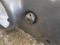
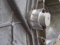
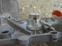
Here are some photos of my attempt at this that may be helpful. I wanted to be able to mount the slave without altering the alternator cover and have external bleed and hose connection. It worked but overnight the fluid leaked out and so the idea was put back under the bench for another day when my machining skills have improved .

P1020535.JPG P1020538.JPG P1020537.JPG
 
Once again thank you for your time.
I have made my own measurements Mr Riggs and I can see what you're talking about. Space is limited.
Did you take your cylinder bore depth measurement from the original worm drive mechanisms total lenght or did you arrive at another measurement based on some other restraint?

Dan

If I remember right, the body can't stick out any more than 7/8" off the side cover without hitting the case. Since the bore diameter is close to the size of the stud on the other end, the depth of the bore needs to be less than 7/8" or the body will be weakened. I eyeballed it and determined the bore needed to stop about this far from the back wall. [You can't see it but I'm holding my thumb and index finger close together in front of my face to show the distance.]
 
LOL I can see it in my head just fine. I had come to .859 based on the 11/32 hole needed for the banjo. So .875 is real close. Thanks Mr Riggs
 
I too had thought I'd like to use the original threaded holes. Instead of having the banjo directly above I'm planning to put it at about 10 o'clock so the original bolt holes can be used.
 
Yup, and that's why a brake caliper piston might be just the ticket and they usually have a square section seal.

Cheers,

Pete
 
Man, I suck at Fusion. My first day on this program. Still, I can only get better I guess.

So the slave will be from round stock. Yet to ad the banjo bolt hole, I'm playing with angle of placement still.

Screen Shot 2017-03-21 at 7.31.00 PM.png
 
If you are using Fusion360 then you should be able to import this solid model (step) of the xs650 engine. I found it to be amazingly accurate in determining clearances.

https://grabcad.com/library/yamaha-xs650-engine-1

I went through this about a month or so, unfortunately I am nowhere near my home PC so I can't share too many details... our designs are similar, although for ease of machining I've chosen to have my port go axially through the cover... I also managed to squeeze in a 28mm piston, which I think is a good match for a 12.9mm master cyl. Not shown is a third adapter piece that I will need to machine to interface between the piston and pushrod. The idea with the third piece is that it will be easier to tweak that piece to get the clearances needed then having to disassemble the actuator.

No I have not assembled it or tried, won't be able to do so for a week or so...

:cheers:

IMG_0163.JPG
 
Last edited:
LOL great to see I'm on the right track. Looks like you have done a fine job on this. Please let me know how you do next week.
Forgive my lack of understanding but wouldn't bleeding the system prime the piston to a perfect fit? Much like bleeding slave cylinder on your disc brakes.

Thanks for the xs650 engine. I'm sure it will be handy in the future.
 
Cool Beans!
So to put some numbers on this, as I'm a numbers kind of guy, the 12.9mm MC combined with a 28mm slave will provide a movement ratio of (12.9/28)*(12.9/28) = 0.21. So if the MC piston moves 1/2" (call it 13mm), you will get (0.5*0.21) = 0.10" (2.7mm) clutch plate movement.

From here (http://xs650temp.proboards.com/thread/17567/bolt-on-hydraulic-clutch-conversion)
I believe Mr. Riggs numbers were using a 9.5mm Magura MC with 13.8mm travel, and a 1" (25.4mm) slave. This yields a movement ratio of 0.14, and a clutch plate movement of 1.9mm.

That's over a 40% difference - BUT I CANNOT CONFIRM THE 12.9MM MC PISTON TRAVEL. From the same thread, another gent measured the stock pulley-screw measurement at 2.08mm.

I would assume (that word has bit Me in the butt more than once...) that the 2.7mm clutch plate movement would assist finding neutral a little easier, but would also have a stiffer pull?
 
LOL great to see I'm on the right track. Looks like you have done a fine job on this. Please let me know how you do next week.
Forgive my lack of understanding but wouldn't bleeding the system prime the piston to a perfect fit? Much like bleeding slave cylinder on your disc brakes.

Thanks for the xs650 engine. I'm sure it will be handy in the future.
Yes I think you are correct but the piston in my design is only 19mm high so it is in my best interest to minimize freeplay so I'm not wasting stroke to adjust out the free play... By using an adapter that is easily removable I should be able to tweak the engagement so there is minimal free play... Thats my theory...
 
Cool Beans!
So to put some numbers on this, as I'm a numbers kind of guy, the 12.9mm MC combined with a 28mm slave will provide a movement ratio of (12.9/28)*(12.9/28) = 0.21. So if the MC piston moves 1/2" (call it 13mm), you will get (0.5*0.21) = 0.10" (2.7mm) clutch plate movement.

From here (http://xs650temp.proboards.com/thread/17567/bolt-on-hydraulic-clutch-conversion)
I believe Mr. Riggs numbers were using a 9.5mm Magura MC with 13.8mm travel, and a 1" (25.4mm) slave. This yields a movement ratio of 0.14, and a clutch plate movement of 1.9mm.

That's over a 40% difference - BUT I CANNOT CONFIRM THE 12.9MM MC PISTON TRAVEL. From the same thread, another gent measured the stock pulley-screw measurement at 2.08mm.

I would assume (that word has bit Me in the butt more than once...) that the 2.7mm clutch plate movement would assist finding neutral a little easier, but would also have a stiffer pull?
Pago, by sticking wires and prodding with welding wire etc I was able to guess somewhere around 12mm or so... So I'm hoping your math is correct...:D
 
Metal, since you've undertaken to learn the art/skill of 3D modelling, one of the added benefits is that if you have access to a 3D printer you should be able to print a 1:1 model in a suitable plastic (PLA, ABS etc) of your actuator and mount it to the cover. That will further confirm if you are on the right track.

I'll post some pics of that on my build thread and crosslink next week...

:cheers:
 
Just an FYI for you guys. My current pressure plate displacement is 0.050" (1.25mm). In all my clutch worm and cable experiments, I don't think I ever exceeded 0.058" (1.5mm) of pressure plate displacement...
 
Just an FYI for you guys. My current pressure plate displacement is 0.050" (1.25mm). In all my clutch worm and cable experiments, I don't think I ever exceeded 0.058" (1.5mm) of pressure plate displacement...

2M - that is good information - sorry if I misled people earlier with my thought about push-rod displacements of up to 0.100".

Also - many folks might not know it but most public libraries now have 3d printers available and they will print your files - often for free!

Pete
 
I used a Kawasaki slave with a 38 mm bore and a 14 mm master cylinder. It has a 4 position adjustable clutch lever. The amount of pressure plate travel is directly proportional to how much you stroke the master cylinder piston. The ratio of master to slave cylinder bore size will determine how much finger effort is required. To calculate that ratio you must first calculate the surface area of the piston. You can't just compare the bore sizes. With my lever in the #4 position I get .100" of pressure plate travel but the lever is pretty far away from the handlebar for my short fingers. The #1 position is more comfortable for me and provides .085" of pressure plate travel. Time will tell if that's enough to give full disengagement but as 2M says the stock worm only gives .058" of travel so I'm optimistic. The seal in the picture is supposed to be 1 piece. Kawasaki mounts the seal to the piston and it slides in the bore where most brake calipers mount the seal in the bore and the seal slides on the piston. It seems either design would work.

20170129_112337_zpsaibk6xa4.jpg


20170128_131602_zps34wacdnl.jpg


Not as clean looking as the hidden slave you are discussing here but also not a huge hideous lump that is susceptible to damage in a tip over.

20170129_124354_zpssqh35qdg.jpg
 
Last edited:
Back
Top