Thanks Scott.Looks great Jim. That's a lot of uglies gone bye bye.
-
Enjoy XS650.com? Consider making a donation to help support the site.
XS650.com receives a small share of sales from some links on this page, but direct donations have a much greater impact on keeping this site going.
You are using an out of date browser. It may not display this or other websites correctly.
You should upgrade or use an alternative browser.
You should upgrade or use an alternative browser.
Jim's 1980 SG Miss September
- Thread starter Jim
- Start date
Out of a gun.
Only if it's prepped and ready to shoot
Nope
 had all this green stuff growing on it when I picked it up..........its called moss we have a lot of it up here in the NW
 The whole bike had it on it but for the price I needed a new project to tinker with.........still looking for a 650
Engine Buildup.
The paint dried overnight. It's actually more of a semi-gloss now... which some people warned me the POR engine paint might do. It kinda bums me. But on the other hand, it's more in line with the finish that came out of the factory. On the bench ready for reassembly....


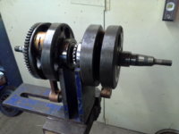
I forgot to mention before, but I cleaned and inspected the "innards" as I removed them. Here's the crank on the V blocks....

Runout is about .0005 which is a little more than I wanted, but still a lot less than the .002 max the book calls for. Reinstalled the crank and tranny, along with new seals.....

And that's as far as I can go. I've spent the last hr. hunting for my gasket sealer so I could close the cases up... no joy. Guess I'm dead in the water 'till I can go get some tomorrow.
The paint dried overnight. It's actually more of a semi-gloss now... which some people warned me the POR engine paint might do. It kinda bums me. But on the other hand, it's more in line with the finish that came out of the factory. On the bench ready for reassembly....
I forgot to mention before, but I cleaned and inspected the "innards" as I removed them. Here's the crank on the V blocks....
Runout is about .0005 which is a little more than I wanted, but still a lot less than the .002 max the book calls for. Reinstalled the crank and tranny, along with new seals.....
And that's as far as I can go. I've spent the last hr. hunting for my gasket sealer so I could close the cases up... no joy. Guess I'm dead in the water 'till I can go get some tomorrow.
Last edited:
I like the finish Jim. Looks good to me.
Nice work!
Nice work!
Meddy
XS650 Addict
Plenty of time spent on it Jim, but not much progressThanks Mick. Any progress on yours since your road trip?
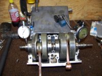
Can't. I made my V block fixture to fit Lycoming cranks and cams.... it won't close down enough to fit the inner journals. Here's how I did it.Jim, check your crank runout with the middle bearings on V-blocks...
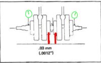
Call the bearings 1 thru 4.... Mount crank on 1 and 4.... measure TIR at 2 and 3 (pictured). Mount crank on 1 and 3... measure TIR at 2 and 4. Mount on 2 and 4.... measure TIR at 1 and 3. Bearings are cleaned and dried, with outer races rotated 90deg and checked again.
Worst reading I got at any given point was about a half a thou.
This is how Lycoming wants their cranks checked. I figure that's at least as good as Yamaha's way of doin' it.
Last edited:
Ah! Nice to see your motor going together Jim! By the way I like the way the paint turned more satin than gloss, I think it looks more like nice clean aluminum.
... I made my V block fixture to fit Lycoming cranks and cams.... it won't close down enough to fit the inner journals. Here's how I did it...
Worst reading I got at any given point was about a half a thou...
Well, that was thorough. Probably OK then.
For the interested, here's an alternate way, using the inverted upper case half.
Note that the end bearings should be removed to do this, so that they're not influencing any runout readings...

Just Ponderin'....
OEM cam chain showed up from Boats.net today. It came with it's own master link. I wish they'd have said that... I wouldn't have spent the extra 4-5 bucks for the link.

Anyway.... just for sh$ts and grins, decided to compare with the old chain...

This engine has right at 20,000 miles on it. Since it took two sticks of dynamite to split the cases, I'm assuming this is the original chain.
So, we have about half a link stretch in 20K mi. 36 teeth on the cam sprocket means 10deg per link... so, about 5deg of stretch. But half of that chain (and stretch) goes to the crank and half goes back to the cam. So actually, it's about 2 and half degrees at the cam which is about 5deg. at the crank. Valve timing is retarded about 5deg. I'm not sure how much of an affect this has on performance... but there's gotta be some power loss associated with that.
Where am I going with this? Nowhere.... I just thought it was interesting.
OEM cam chain showed up from Boats.net today. It came with it's own master link. I wish they'd have said that... I wouldn't have spent the extra 4-5 bucks for the link.
Anyway.... just for sh$ts and grins, decided to compare with the old chain...
This engine has right at 20,000 miles on it. Since it took two sticks of dynamite to split the cases, I'm assuming this is the original chain.
So, we have about half a link stretch in 20K mi. 36 teeth on the cam sprocket means 10deg per link... so, about 5deg of stretch. But half of that chain (and stretch) goes to the crank and half goes back to the cam. So actually, it's about 2 and half degrees at the cam which is about 5deg. at the crank. Valve timing is retarded about 5deg. I'm not sure how much of an affect this has on performance... but there's gotta be some power loss associated with that.
Where am I going with this? Nowhere.... I just thought it was interesting.
hotshoe
XS650 Enthusiast
Jim, just wonderin, someone once told me chains do not stretch, they wear. If you wear .002 off the pin that goes through the roller on a chain and that chain is 104 links long then the chain would be .208 inches longer, if .004 was worn off each pin the chain would be .416 inches longer, but if you measure the distance from center point to center point on the fixed pins the distance will be the same as a new chain, what do you think?
Yeah, what we call stretch is actually wear on the pins and the holes. The links themselves don't actually stretch.Jim, just wonderin, someone once told me chains do not stretch, they wear. If you wear .002 off the pin that goes through the roller on a chain and that chain is 104 links long then the chain would be .208 inches longer, if .004 was worn off each pin the chain would be .416 inches longer, but if you measure the distance from center point to center point on the fixed pins the distance will be the same as a new chain, what do you think?
That is very interesting, Jim. It makes me wonder how much cam lag (I just made that up) is introduced when chain stretch (wear) is compensated for with the tensioner, relative to the position of the crank, and how much this influences combustion. Theoretically, you could time your motor perfectly, at the crank/generator, but when your points say "FIRE!", your pistons could be off (before/after TDC), especially at higher RPMs. This could still happen with a crank-fired ignition (like HHB's CDI), only in reverse. The pistons are in the right place, at the time of ignition, but the valves are off. It goggles the mind (mine). I wonder if there's room between the cylinders for a gear train that would eliminate the cam chain entirely? Somebody's got to have an engine apart that could tell if such engineering heresy is even possible....
You mean like this...I wonder if there's room between the cylinders for a gear train that would eliminate the cam chain entirely?
I think the easier solution would be adjustable chain tensioners on both sides of the cylinders. You could balance the stretch that way.
I seem to remember that Honda sold a performance bike some years ago that had a gear driven camshaft.
It was pretty complex and hard to work on from what I remember.
It was pretty complex and hard to work on from what I remember.
Yup. Although I was thinking something a little less Rube Goldbergesque.... something, maybe a little more drop-in. But I think you'd have to replace the sprockets on the cam and crank with more conventional gears. A valid concept, perhaps, but a re-invention of the wheel. And we know they are round.... Better to pursue the tensioners on both sides idea, or better still....leave it alone.You mean like this...
Your restoration, by the way, is looking fantastic. And your mechanical expertise is something I can only aspire to. You're encouraging our builds to a higher level of excellence. Keep it up!
JRP has a gear driven cam VFR750F Honda, all those gears make noticeable whirring noise.I seem to remember that Honda sold a performance bike some years ago that had a gear driven camshaft.
It was pretty complex and hard to work on from what I remember.
JRP has a gear driven cam VFR750F Honda, all those gears make noticeable whirring noise.

Yeah! That’s the bike I was remembering!
Sump Screen and Cover
Seems I'm gettin' worse about my "before" pics... as if I wasn't bad enough already.
Anyway.... the sump cover apparently had been removed before with a sharp screwdriver and hammer. The leaks got so bad that the PO actually used two gaskets... and that allowed the cover to get bent to hell around the fastener holes. Ol' dipstick forgot to get some before pics, but here it is after close to an hour with 400 wetordry and wd40....

Good as new. Also re-surfaced the lower case mating surface. While I was in the sanding mood, I went ahead and sanded down the new cam chain per one of XSJohns mods. Here's the chain straight out of the bag.....

The links are stamped out steel and the stamping process leaves a rough edge that "saws" on the guide and tensioner until they finally rub the rough edges down. XSJohn believed (and I agree) that the guide and tensioner life would be extended if you smooth the links down before you install it. A blue roloc disk made short work of it....

The sump screen looks like brand new after I soaked it in stoddard cleaner overnight. No damage to it whatsoever. Anybody know if this is Mikes, OEM... other?


Seems I'm gettin' worse about my "before" pics... as if I wasn't bad enough already.
Anyway.... the sump cover apparently had been removed before with a sharp screwdriver and hammer. The leaks got so bad that the PO actually used two gaskets... and that allowed the cover to get bent to hell around the fastener holes. Ol' dipstick forgot to get some before pics, but here it is after close to an hour with 400 wetordry and wd40....
Good as new. Also re-surfaced the lower case mating surface. While I was in the sanding mood, I went ahead and sanded down the new cam chain per one of XSJohns mods. Here's the chain straight out of the bag.....
The links are stamped out steel and the stamping process leaves a rough edge that "saws" on the guide and tensioner until they finally rub the rough edges down. XSJohn believed (and I agree) that the guide and tensioner life would be extended if you smooth the links down before you install it. A blue roloc disk made short work of it....
The sump screen looks like brand new after I soaked it in stoddard cleaner overnight. No damage to it whatsoever. Anybody know if this is Mikes, OEM... other?
Last edited:
Similar threads
- Replies
- 30
- Views
- 2K


