Kent Money's First Build - "Beginner's Luck"

I asked him if these used any loctite/bonding agent when pressing the halves together and he said they didnt. He estimates he used about 4-5 tons to press them together...

hope it doens't cause problems later.

Will be posting pics of my engine all soda blasted and clean. Found a place here in Morgan Hill, CA that does soda blasting. Cost me $58 to do the whole engine pretty much!
 
Time for updates:

Got the engine soda blasted and it turned out good. here are some pics of me hosing them down afterwords.

IMG_0920.jpg


Started assembling from the bottom up! Dont worry, I flipped the gasket around ;)

IMG_0923.jpg


Also worked on the head and lapped up the valves. I decided I would skip porting this time around, I wanna get riding!

IMG_0925.jpg


So, i got the crankcase all buttoned up with the new rephased crank. Cleaned out all the innards too. Man, it was a bitch getting the crank bearings lined up with the holes/oil feeds, but I got it done.

Managed to get the new oversized pistons in too, and the new rephased camshaft on top of that. Hopefully I got the timing right...

IMG_0930.jpg


Then I started masking for paint.

IMG_0935.jpg


Got the masking done and started to paint. Got some Duplicolor Engine enamel. Put on about 3ish coats on today and ran out of paint. Will get another can tomorrow and finish off the bottom and some final coats.

IMG_0942.jpg


Then I started working on the tank which I have been putting off; please ignore the rust! Got a step-drill and made the bungholes (heh, heh, Beavis) on the top for the fuel sight. I also made a bunghole at the bottom left corner to maximize my fuel usage. I fitted some petcocks I've had but I don't know if I like them; sorta too clunky, big and chrome for my taste. Then I fitted some brass fitting and an inline fuel valve. Which do you guys like better? I'm leaning towards the inline valve with an inline filter...

IMG_0937.jpg

IMG_0941.jpg


And here is how she stands now. I moved the wheels alllll the way to the back of the dropouts, and I'm gonna make some spacers to go in front of them so that I wont have to run a chain tensioner. I also ordered some sweet 7/8 bars off eBay, so I will have them on shortly. Lastly, I also started on the speedo mount. Lastly, I am thinking that the bike will be primarily black with either a red-orange tank or white tank, not sure.

IMG_0939.jpg

IMG_0946.jpg

IMG_0947.jpg
 
Last edited:
Moving a long and time for updates!

I finished the PMA install and it more or less went without a hitch. Was a little hard getting the woodruff key to be the right size but it worked out.

IMG_0980.jpg


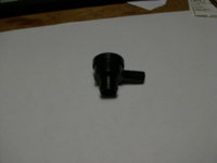
Then I got a PCV from Autozone and put it on the breather hose. The PO had a filter there but I don't think I'll need it if I route the hose so it drips on the pod filters. Also, this isn't a spring loaded PCV so hopefully it won't cause any undesirable pressure in the engine...

IMG_0981.jpg


I got the new bars put on and I had my friend weld the bungs into the tank, so now I'm just gonna Kreem it and primer it. I also handmade a speedo mount out of some thick aluminum.

IMG_0988.jpg

IMG_0991.jpg

IMG_0990.jpg


BONUS LIFESTYLE PICS: from a recent car show
IMG_0968.jpg
 
The pvc valve won't work well, the heavy steelball inside can't react fast enough. What you want is a power brake check valve. #80190 It's on the rack in the Help section.
Here's a pic.
 

Attachments

  • LostFile_JPG_65018528.jpg
    LostFile_JPG_65018528.jpg
    113.8 KB · Views: 160
thanks leo, I'll look into that. so what mechanism does the power brake check valve employ?

what do you mean by "its on the rack in the Help section" ?
 
I like your bike looks good, I had that style bars they look great but after about 10 min. of riding my wrists would start to hurt 30 min. down right pain. I put the same style but angled back slightly at the grips they were great. You might not have that problem. Nice build keep up the good work.
 
where did you get your old black bars from ?
I got them off eBay. I am selling them, however, so let me know if you want them!

Good job man. We thought we lost you there for a few months.
Thanks Joel! I did have a bit of a hiatus but I am back on it now that the engine is running. I have a friend who is supposed to come over and help me with some welding, but he has been a bit flakey so that's slowing things down.

Great work. What kind of seat are you going with?

Are those rebel shocks?
My plan is to make my own seat. Im gonna cut out a flat pan, layer it with small-cell camping pads, then shape and contour it, and try to upholster it. I may end up getting the upholstery done by a professional, though. Hopefully it'll be big enough to accomodate a passenger, too.

The shocks are not rebels. They are the shocks available from MikesXS, I believe they are 11.75" or something like that.


I like your bike looks good, I had that style bars they look great but after about 10 min. of riding my wrists would start to hurt 30 min. down right pain. I put the same style but angled back slightly at the grips they were great. You might not have that problem. Nice build keep up the good work.

I totally know what you mean. All my BMX bars had sweep, so I may have to get use to the zero sweep on these bars. I hope I don't run into the same problems you did with the pain. Otherwise I'll get another set fabbed up for me from the same guy. I may go a little taller next time too.
 
Last edited:
Gonna play a little catch up:

So here is the obligatory sparks-a-flyin' shot. I was cutting out the stock cross supports on the seat rails. I'm gonna relocate my own.
photo-25.jpg


Here is how it looks as of lately. Got a new front brake rotor, new braided single-piece brake line, new clutch lever, new brake lever/master cylinder. Also got a sweet cruise control modification put on the throttle.
photo-30.jpg


Here is another view. The electrical box in the next photo will slide right under the seat rails.
photo-31.jpg


My buddy who does metal work for a living fabbed up this electrical box for me. Will hold a full size battery, key switch, solenoid, fuses, etc.
photo-42.jpg


And lastly, you may have read in another thread about the issue I was having with starting the motor for the first time. I hooked up the Pamco and was only getting some backfiring; it wouldn't start. So, instead of doing the smart thing and just setting up the Pamco in a different way, I assumed that my valve timing must have been off. Hence the following picture. I ended up pulling out the engine, taking off the valve cover, buying dial indicators and shit, and it was all for no reason. It turns out that my valve timing was off by about only 1 degree, so it was already good! At least now I know the specs on my engine :laugh: I buttoned the engine back up and set up the Pamco differently this time, and it worked perfectly.
photo-41.jpg


As you can see, I did that on a budget. I printed out a free degree wheel and slapped it on a piece of cardboard; a bit crude but it worked. I got the dial indicators and the mounting equipment for about $25 total from harbor freight (and the dial indicator is actually pretty accurate!). And lastly I made a piston stop out of a piece I found at the auto store. Let me know if you have any questions. It's a very economical and accurate way of finding out the true TDC of your engine.
 
Here is a picture of my old BMX buddy who has been helping me with all the welding stuff; he does it for a living now. Managed to weld the new cross supports for the seat rails. I will be attaching the electronics box to them.

photo-44.jpg


Here is a picture of the stance.
photo-43.jpg
 
Gonna play a little catch up:

And lastly, you may have read in another thread about the issue I was having with starting the motor for the first time. I hooked up the Pamco and was only getting some backfiring; it wouldn't start. So, instead of doing the smart thing and just setting up the Pamco in a different way, I assumed that my valve timing must have been off. Hence the following picture. I ended up pulling out the engine, taking off the valve cover, buying dial indicators and shit, and it was all for no reason. It turns out that my valve timing was off by about only 1 degree, so it was already good! At least now I know the specs on my engine :laugh: I buttoned the engine back up and set up the Pamco differently this time, and it worked perfectly.
photo-41.jpg


As you can see, I did that on a budget. I printed out a free degree wheel and slapped it on a piece of cardboard; a bit crude but it worked. I got the dial indicators and the mounting equipment for about $25 total from harbor freight (and the dial indicator is actually pretty accurate!). And lastly I made a piston stop out of a piece I found at the auto store. Let me know if you have any questions. It's a very economical and accurate way of finding out the true TDC of your engine.

So how exactly does this work for you. I'm trying to figure it out based on your pic, but I'm not sure I'm seeing everything. It looks like your piston stop is threaded. If so, how do you know when you've reached TDC? Or are you not screwing it in and simply using the dial indicator to find the high point and putting the card at the TDC mark and then adjusting from there? Just trying to figure out what looks like a very cool system.
Thanks
 
Here is one way to look at it

Step 1: Finding True TDC
The tool that I made is two parts: a spark plug adaptor that I found at the auto store ($4) and some random bolt I had lying around. The adaptor is threaded the same size as the spark plug, so you just screw it in to the engine. I tapped a hole that was in one end of the adaptor and just screwed the bolt all the way in. You just want to make sure that this bolt protrudes well into the top of the cylinders, so that if you were to rotate the crank the piston would hit it and stop on its way up to TDC.

This is how you use it. You must have a degree wheel on the crankshaft and a pointer made out of a coat hanger set up in a way as to help you read the degree wheel. (see the picture) What you want to do is rotate the crank so that the piston is located somewhere B(efore)TDC. You can approximate this by peeping in through the spark plug hole with a flash light; you will see the piston begin to approach TDC as you rotate the crank. At this point stop rotating the crankshaft and screw in the tool you made. Now slowly continue rotating the crankshaft CCW (towards TDC) until it bumps on the end of the bolt protruding into the cylinder. Be careful not to gouge your piston. Make sure the piston is resting against the bolt and set the degree wheel to 0 degrees. Now you unscrew the tool you made and rotate the crank to a point somewhere A(fter)TDC. Again you will screw in the tool and rotate the crank CW until the piston bumps on the bolt. You must read the degree wheel as the piston rests against the bolt. Take this number and half it. The resulting number is the location of True TDC on the degree wheel. You must ensure that the degree wheel does not spin independent of the crankshaft while you perform all these procedures, or you will need to start over.

Step 2: Valve Timing
The purpose of the dial indicators is to let you know when the valves begin to open, and to measure the amount of valve lift. The idea is that you want your cam and its lobes to be spinning in a way that all opening and closing of the valves occurs at the optimal time within the 4-stroke phases. So you must set your dial indicators perpendicular to the surface of the valve-spring retainers. What you do is set the degree wheel so that 0 degrees is at TDC of the crank. Rotate the crank 1.5 full revolutions going CCW. This is to make sure there is no slack in your cam chain. As you come around to 1.5 revolutions start to carefully monitor the dial indicator to see when the valve starts to open. This should occur at 36 degrees BTDC (this spec is true for my 1981 engine, at least).

There is another way involving the lobe centers, see my other thread for details.
 
Back
Top