-
Enjoy XS650.com? Consider making a donation to help support the site.
XS650.com receives a small share of sales from some links on this page, but direct donations have a much greater impact on keeping this site going.
You are using an out of date browser. It may not display this or other websites correctly.
You should upgrade or use an alternative browser.
You should upgrade or use an alternative browser.
Large Spine Frame XS650 / Egli / Rau / Cafe Racer
- Thread starter rehar
- Start date
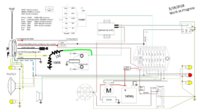
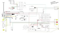
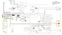
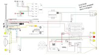
I'm second guessing myself here... the more I think about it, the less I'm convinced the tach will "see" a pulse off that ground. On the "old" ign system, that negative was a power feed to the points, which then supplied the ground..
Now I'm back to thinkin' tie it to the green wire through a 5K resistor like we did with the Dynon. I'll ponder some more....
Now I'm back to thinkin' tie it to the green wire through a 5K resistor like we did with the Dynon. I'll ponder some more....
Yeah... like Steves cat drew above I don't think the size of the resistor(s) is that critical (based on their claim you won't hurt it), as long as you stay above the 4.7K they supplied
It would be nice to know what circuit is in the tach's input line. Could be capacitor isolated, resistor isolated, or both. If it has reverse-polarity protection, or not. Or wired direct to a frog's leg, which kicks something expensive...
Just about all microcircuits I've dealt with on aircraft were isolated with a transformer.Could be capacitor isolated, resistor isolated, or both.
Or..... it could be that.Or wired direct to a frog's leg, which kicks something expensive...
rehar
rehar
Zedhead
XS650 Enthusiast
The headlights for the Suzuki SV650 naked, and later model Suzuki Bandit are plastic bodies and plastic lenses, and they're light! ;-)Any good ideas out there for Plastic 5-3/4" headlight/bulb? I'm afraid the glass lens on most lights would crush/crack mounted in the CNC/Billet frame...
rehar
rehar
Zedhead - thank you for the tip. It's so hard to tell by reading ebay descriptions and blank stares when I go into the local autoparts stores, that I put that on the back burner. I'll check that out.
rehar
rehar
rehar
rehar
Making a wire harness from scratch: It's taking me alot more time than I thought it would and it helps if you have the right tools.
This might not be too exciting to post about, but I was so impressed with the results - of having the right tool for crimping.
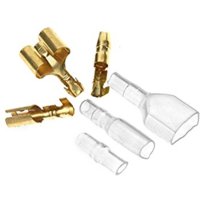
I needed some good crimp connectors. I liked these - got them off amazon, they have two crimp regions, one for the conductor and one for the insulation. These also came with the little boots to make a good water resistance joint.
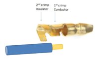
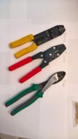
When I started in the garage in the morning, I had the yellow tool on the left. Do your self a favor and just through it away. $23 bought the Red tool in the center. It has a little shape in the middle for forming the crimps and is alot thicker. This tool makes perfect, production quality joints. The last tool on the right - $15, I bought for the larger crimps used on the 8 AWG battery / power cables.
The connectors I need to use are for larger wire than the M-Button. This is a problem. Found a great document: IPC/WHMA-A-620 which gave me the idea to add filler material in the crimp zone. Filler material - can be extra wire for example. Makes the wire thicker at that interface, and can provide extra strain relief.
In the morning with the yellow tool:
This could have been done with a separate wire, I used a single piece and folded it back upon itself.
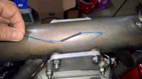
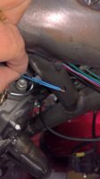
Then applying the connector, and crimping, realized how poor the yellow tool was. I had to result to soldering the joint. I think the results were acceptable, but fussy and takes a bit of time. Ended up using needle nose pliers, they were better than the yellow crimp tool. First fold over the material, then solder.
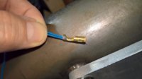
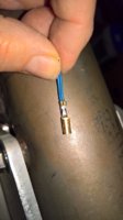
End with the shrink wrap.
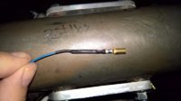
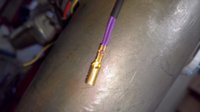
Then after I bought the RED tool, purple wire, same doubling of material, then Crimp once, twice - no soldering - done.
Very nice joint. Faster, cleaner, easier, better. Very professional looking.
This might not be too exciting to post about, but I was so impressed with the results - of having the right tool for crimping.
I needed some good crimp connectors. I liked these - got them off amazon, they have two crimp regions, one for the conductor and one for the insulation. These also came with the little boots to make a good water resistance joint.


When I started in the garage in the morning, I had the yellow tool on the left. Do your self a favor and just through it away. $23 bought the Red tool in the center. It has a little shape in the middle for forming the crimps and is alot thicker. This tool makes perfect, production quality joints. The last tool on the right - $15, I bought for the larger crimps used on the 8 AWG battery / power cables.

The connectors I need to use are for larger wire than the M-Button. This is a problem. Found a great document: IPC/WHMA-A-620 which gave me the idea to add filler material in the crimp zone. Filler material - can be extra wire for example. Makes the wire thicker at that interface, and can provide extra strain relief.
In the morning with the yellow tool:
This could have been done with a separate wire, I used a single piece and folded it back upon itself.


Then applying the connector, and crimping, realized how poor the yellow tool was. I had to result to soldering the joint. I think the results were acceptable, but fussy and takes a bit of time. Ended up using needle nose pliers, they were better than the yellow crimp tool. First fold over the material, then solder.


End with the shrink wrap.

Then after I bought the RED tool, purple wire, same doubling of material, then Crimp once, twice - no soldering - done.
Very nice joint. Faster, cleaner, easier, better. Very professional looking.

Last edited:
rehar
rehar
Venting: I hate wiring. One step forward, two steps backward. Pre-existing connectors are always in the wrong place. The cables I just put together are too short or too long. Realization that Throttle cables aren't going to coexist in the same space as the electrical cables, etc...
Need to order more tubing for the headlight cable, which just became independent from the rest of the main harness.
GPS Speedo wires and their connectors and the inverter for the small EL lighting - WHY did they not integrate this?
Putting a positive spin on it, wow, I'm sure learning ALOT.
The 1into2 throttle cable: Anyway to convert the Mikuni VM34s into a SINGLE throttle cable? Like the 35mm Keihin CR Carbs?
Venhill makes a cable kit that splits the cables 2 into 1. Emgo sells the splitter separately. It is very compact and hides easily under the center bar. The Venhill kit has all the cable ends and bulk cable. I know what your saying about wiring. It just turns out to be a continuous on line order. Auto parts and Hdw store stuff just doesn`t do the trick. I try to encase the wires in a mesh covering. This material is pretty forgiving if you have to make a change or add a wire or two. I`ve followed this build from the start. Great Work!
P.S. Don`t forget the cable adjuster like I did last week.
http://www.venhillusa.com/venhill-u...ottle-motorcycle-cable-kit-with-junction.html
P.S. Don`t forget the cable adjuster like I did last week.
http://www.venhillusa.com/venhill-u...ottle-motorcycle-cable-kit-with-junction.html
Try these guys for throttle cable splitters. 1-2, 1-3, 1-4.
http://www.greenskyadventures.com/throttle_cable/throttlecable.htm
http://www.greenskyadventures.com/throttle_cable/throttlecable.htm
rehar
rehar
Trying a few different things. Its a very tight fit, with trade-offs.
I do have a 1-2 split cable. The 1-2 splitter body I have is 4.86" long X .63" diameter.
Main Wiring Bundle is .55" diameter and has to really squeeze into position.
The splitter fits, barely, in one position and only one.
It's putting alot of pressure on the connectors as the come out from the .55" bundle.
I'll post some pics when I get this puzzle figured out.
Speaking of CONTINUOUS ONLINE ORDERING... Your not kidding! That's exactly what it feels like.
rehar
rehar
Got the front of the bike more or less wired.
Used the M-Button up front, placed inside the left clip-on. Adds more fussiness up front which I didn't want but... Gotta move forward. (Benefit, streamlines the harness behind the steering head.)
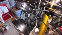
Cables fo around the head on both left and right side. Square item is the inverter for the EL backlighting on the GPS Speedo. A few more wires remaining. Need to complete the M-Unit wiring back in the seat tray to really know what works/how. Although the M-Unit is well documented, there are some uncertainties about how to integrate the GPS speedo and M-unit, until the wiring electrics are a bit more operational. All fits between the engine tope head bracket/plates now.
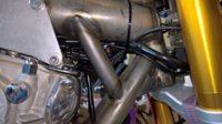
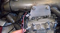
The infamous Yellow Tach wire - wrapped and heat shrinked around a spark plug cable. See how that works as a starting point.
I'll finish this up a bit more, later.
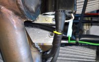
The tray: Maybe next weekend.
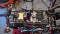
Used the M-Button up front, placed inside the left clip-on. Adds more fussiness up front which I didn't want but... Gotta move forward. (Benefit, streamlines the harness behind the steering head.)

Cables fo around the head on both left and right side. Square item is the inverter for the EL backlighting on the GPS Speedo. A few more wires remaining. Need to complete the M-Unit wiring back in the seat tray to really know what works/how. Although the M-Unit is well documented, there are some uncertainties about how to integrate the GPS speedo and M-unit, until the wiring electrics are a bit more operational. All fits between the engine tope head bracket/plates now.


The infamous Yellow Tach wire - wrapped and heat shrinked around a spark plug cable. See how that works as a starting point.
I'll finish this up a bit more, later.

The tray: Maybe next weekend.

...The infamous Yellow Tach wire - wrapped and heat shrinked around a spark plug cable. See how that works as a starting point...
Justa 'nother FYI. The wire wrap can be one of 4 different patterns.
Winding towards the plug, or winding towards the coil.
Either with winding clockwise or counterclockwise.
Each one of these will produce a unique spike waveform...
rehar
rehar
 I will keep that in mind.
Zedhead
XS650 Enthusiast
And, of course, you could always reverse the winding direction halfway along its length - ie do half running anti-clockwise band the rest clockwise. Or half of it running towards the plug, and half back towards the coil. Or a combination of those... Electronics makes my head hurt...
rehar
rehar
Quick update:
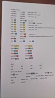
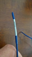
I was having trouble tracking which wire was what - especially after things sitting for a week, so I decided I should label the wires (permanently, for future debug/maintenance, etc). There are cable / label marking systems that can be printed and applied. My son has some white paper with weak adhesive on the back side I can run through the ink jet printer. Then I ordered some clear heat shrink tubing. So I used the combination of paper printed label, then heat shrink over it. Worked pretty well. Here's a shot of the sheet before cutting it up and a sample of a handwritten mark with the heat shrink - to test it out.
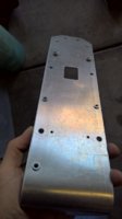
Installed some M5 and M6 PEMNUTs to the tray.
and made some good progress. Inverter for the gauge, Starter solenoid and Battery have yet to be integrated.
![WP_20180415_16_01_57_Pro[3282].jpg WP_20180415_16_01_57_Pro[3282].jpg](https://www.xs650.com/data/attachments/109/109327-b22bb6155899e38bdad62f0f99f3abb9.jpg)
I was having trouble tracking which wire was what - especially after things sitting for a week, so I decided I should label the wires (permanently, for future debug/maintenance, etc). There are cable / label marking systems that can be printed and applied. My son has some white paper with weak adhesive on the back side I can run through the ink jet printer. Then I ordered some clear heat shrink tubing. So I used the combination of paper printed label, then heat shrink over it. Worked pretty well. Here's a shot of the sheet before cutting it up and a sample of a handwritten mark with the heat shrink - to test it out.


Installed some M5 and M6 PEMNUTs to the tray.

and made some good progress. Inverter for the gauge, Starter solenoid and Battery have yet to be integrated.
![WP_20180415_16_01_57_Pro[3282].jpg WP_20180415_16_01_57_Pro[3282].jpg](https://www.xs650.com/data/attachments/109/109327-b22bb6155899e38bdad62f0f99f3abb9.jpg)
Last edited:
Similar threads
- Replies
- 90
- Views
- 9K

