After looking at Gary's diagram Bob, maybe it's off a little and the brown feeds the safety relay. Ohm it with your meter and see if that's the case?
-
Enjoy XS650.com? Consider making a donation to help support the site.
XS650.com receives a small share of sales from some links on this page, but direct donations have a much greater impact on keeping this site going.
You are using an out of date browser. It may not display this or other websites correctly.
You should upgrade or use an alternative browser.
You should upgrade or use an alternative browser.
Mailman’s XS2 a full on restoration
- Thread starter Mailman
- Start date
Sure I can check that.
If Pete recommends that fuse... I'd go ahead and add it. I'm an airplane guy, no such thing as too many fuses. 
72XS2/73TX wiring Symantec


Where the R/W and Br power wires break into 2 brown wires for the coil's it is confusing.......Rhetorical...why have 2 separate colored wires connecting at the base of a bullet connector and then splitting on the other side of the bullet connector and running 2 separate, (power), Br one to each coil. ........Yamaha wired it so the power goes to the coils on Red/White then back to the safety relay on the Brown from where the R/W and Br join together at the bullet connector
Where the R/W and Br power wires break into 2 brown wires for the coil's it is confusing.......Rhetorical...why have 2 separate colored wires connecting at the base of a bullet connector and then splitting on the other side of the bullet connector and running 2 separate, (power), Br one to each coil. ........Yamaha wired it so the power goes to the coils on Red/White then back to the safety relay on the Brown from where the R/W and Br join together at the bullet connector
Last edited:
Hi. What I have done in the past on Petrol pipe unions when I couldn’t stop them leaking is, find a small copper washer, inside dia the same as the hole in the pipe 3mm I guess and outside dia to fit inside the union. Anneal the washer, heat up to cherry red and quench in water, put said washer in between pipe and fitting, nip it up, no more e leak. Hope it helps.I’m a little concerned about cutting any length off of the existing line. Because the length puts the fitting right at the mounting point on the fork leg. It has to hit that at just the right spot because there is a rubber bushing that goes over the fittings and fastens to the leg.
Mailman you may want to read through this thread it relates to the XS2s.
http://www.xs650.com/threads/xs2-wiring-diagram.53244/
http://www.xs650.com/threads/xs2-wiring-diagram.53244/
ith the kill switch off the starter does not work. I went to the starter solenoid expecting to find a red/wight and a blue/white. What I found there was a solid brown and blue/white. What the hay, that shouldn't be. Wires should not change color/number in the middle of a run.Went to my other XS2 that I have the tank off of and look what I found.
At the coils the R/W changes to Brown.That's not cricket.Yamaha played fast and loose with wire colors. Makes a guy wonder what else they might have done. I wonder if Mailman's is same?
Nice job on that coil mounting, Bob !
My simple brake line bender cost me a couple bucks back in the day:

My simple brake line bender cost me a couple bucks back in the day:
To all of you that have taken the time to respond....Thank You! I am considering lots of things right now for the brake line and the wiring.
Ha! Jim suggested the same thing to me. I haven’t got the correct sized copper washer, perhaps a trip to the hardware store is in order.
Thanks GLJ, I’ll give that a read.
Nice! Yeah Scott mentioned that tubing is pretty easy to bend without a fancy bender. I thought you had to have one , or risk collapsing the tube.
Hi. What I have done in the past on Petrol pipe unions when I couldn’t stop them leaking is, find a small copper washer, inside dia the same as the hole in the pipe 3mm I guess and outside dia to fit inside the union. Anneal the washer, heat up to cherry red and quench in water, put said washer in between pipe and fitting, nip it up, no more e leak. Hope it helps.
Ha! Jim suggested the same thing to me. I haven’t got the correct sized copper washer, perhaps a trip to the hardware store is in order.
Mailman you may want to read through this thread it relates to the XS2s.
http://www.xs650.com/threads/xs2-wiring-diagram.53244/
Thanks GLJ, I’ll give that a read.
Nice job on that coil mounting, Bob !
My simple brake line bender cost me a couple bucks back in the day:
View attachment 135351
Nice! Yeah Scott mentioned that tubing is pretty easy to bend without a fancy bender. I thought you had to have one , or risk collapsing the tube.
Minor bends in brake tubing are easy to do by hand but you may need/want a bender for tight ones.
On your coil wires coming out of the harness, the red/white and the brown are crimped together and can't be separated, correct? In other words, you can't unplug the brown from the red/white, they are crimped into the same crimp. I think that is just the way Yamaha fed power into that brown wire, how they branched it off to run to the safety relay. I don't understand what you mean when you said you just capped off that brown wire. Do you mean the other end of it where it comes out of the harness back by the battery box? If so, then that's wrong, that brown needs to connect to the safety relay. It powers it.
On your coil wires coming out of the harness, the red/white and the brown are crimped together and can't be separated, correct? In other words, you can't unplug the brown from the red/white, they are crimped into the same crimp. I think that is just the way Yamaha fed power into that brown wire, how they branched it off to run to the safety relay. I don't understand what you mean when you said you just capped off that brown wire. Do you mean the other end of it where it comes out of the harness back by the battery box? If so, then that's wrong, that brown needs to connect to the safety relay. It powers it.
That wiring diagram is a conclusion from the thread GLJ posted........A continuity test may help but my reservation is where the Red/Yellow and br wire run into the bullet connector at the coil. being joined will trow the test from the Safety relay..........????.
That wiring diagram is a conclusion from the thread GLJ posted........A continuity test may help but my reservation is where the Red/Yellow and br wire run into the bullet connector at the coil. being joined will trow the test from the Safety relay..........????.
Good point Skull. I used to test manufactured homes with a $10 multimeter, no AC power to these homes. My first step was to disconnect any motors and remove the lightbulbs so I wouldn't get any false readings. Any wiring problems had to be repaired the very same day they were found. I was the most hated guy in the plant. Ground fault circuit interrupters (GFCI's) were often wired backwards.
Scott
Last edited:
shawnkva
XS650 Addict
one of these should work too. Price is right.

I don't understand what you mean when you said you just capped off that brown wire.
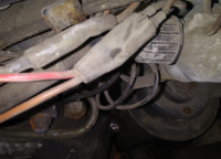
What I did was simply cut the two wires right here , before the connection, then separated the two wires and ran the red/ white wire to the coil. The brown wire was simply taped off and tucked outa the way for the time being. I had a feeling at the time I was going to have to come back and do something with it. I’m not in the garage today. But I intend to redo the wiring. I need to return power to that brown wire for the safety relay and I also want to include a 7.5 amp inline fuse to the power supply to the coil , as per Pamco Pete’s recommendation.
Photo shows where I cut the wires.
Just one more option for front brake line.
I have the one off my parts bike, while not a 10 point show condition I think it is very usable. If for nothing else to prove the problem is in your steel line.


The roughness in the lower picture is not as bad as it looks!
Say the word and it could be in the mail in the morning. And I do know where you live!
Ken in NY
I have the one off my parts bike, while not a 10 point show condition I think it is very usable. If for nothing else to prove the problem is in your steel line.
The roughness in the lower picture is not as bad as it looks!
Say the word and it could be in the mail in the morning. And I do know where you live!
Ken in NY
I'm really surprised you cut those wires, lol. My '78, like your '77, had 2 R/W wires coming out of the harness, one to power each coil. They are actually 2 leads "Y"d off the same wire in the harness, the wire is split into 2 wires. I utilized both for my Pamco install, running one to the new coil and the other to the Pamco red power wire. I added bullet connectors to the Pamco wires so everything just plugged into the original harness connectors. My new coil, like yours, had flat spade connections on it. I made short jumper wires with a flat spade on one end, bullet on the other. Everything is "plug and play" so none of the original wires from the harness were cut or altered.
I'm really surprised you cut those wires, lol. My '78, like your '77, had 2 R/W wires coming out of the harness, one to power each coil. They are actually 2 leads "Y"d off the same wire in the harness, the wire is split into 2 wires. I utilized both for my Pamco install, running one to the new coil and the other to the Pamco red power wire. I added bullet connectors to the Pamco wires so everything just plugged into the original harness connectors. My new coil, like yours, had flat spade connections on it. I made short jumper wires with a flat spade on one end, bullet on the other. Everything is "plug and play" so none of the original wires from the harness were cut or altered.
Yup, that’s what recall on Lucille (‘76 Standard) - a double red/white female connector to which I made my own PAMCO connections.
Pete
What I did was simply cut the two wires right here , before the connection, then separated the two wires and ran the red/ white wire to the coil. The brown wire was simply taped off and tucked outa the way for the time being. I had a feeling at the time I was going to have to come back and do something with it. I’m not in the garage today. But I intend to redo the wiring. I need to return power to that brown wire for the safety relay and I also want to include a 7.5 amp inline fuse to the power supply to the coil , as per Pamco Pete’s recommendation.
Photo shows where I cut the wires.
View attachment 135372
Mailman, now that you have cut those 2 wires it would be a good time to continuity test these circuits..........Doing the test below i can finish with confidence the wiring drawing in that area.
Test the Br wire you cut at the points and at the safety relay. If it is infinity then it should prove the power is going to the safety relay from the R/W to the Br where it joins at the coil Bullet connector.
Also test the R/W on down side of the kill switch and the Br wire at the Safety relay. If infinity the the Br off the relay is joined to the R/W before the Coils and the Br runs along side the R/W the as per my loom..........If full resistance then the power is coming back on the Br wire from where it joins the R/W at the coils.
Just one more option for front brake line.
I have the one off my parts bike, while not a 10 point show condition I think it is very usable. If for nothing else to prove the problem is in your steel line.
View attachment 135373 View attachment 135374
The roughness in the lower picture is not as bad as it looks!
Say the word and it could be in the mail in the morning. And I do know where you live!
Ken in NY
Ken, I don’t know why I didn’t think to check with you. Yes I would be interested! Thank you very much. That line looks better than the one I have.
I'm really surprised you cut those wires, lol. My '78, like your '77, had 2 R/W wires coming out of the harness, one to power each coil. They are actually 2 leads "Y"d off the same wire in the harness, the wire is split into 2 wires. I utilized both for my Pamco install, running one to the new coil and the other to the Pamco red power wire. I added bullet connectors to the Pamco wires so everything just plugged into the original harness connectors. My new coil, like yours, had flat spade connections on it. I made short jumper wires with a flat spade on one end, bullet on the other. Everything is "plug and play" so none of the original wires from the harness were cut or altered.
I cut the connector off so I could isolate the red/white wire. HOWEVER, I intentionally left enough wire on the connector so that it could be soldered back on if I wanted to. ( and I will probably do just that.)
.Mailman, now that you have cut those 2 wires it would be a good time to continuity test these circuits..........Doing the test below i can finish with confidence the wiring drawing in that area.
Test the Br wire you cut at the points and at the safety relay. If it is infinity then it should prove the power is going to the safety relay from the R/W to the Br where it joins at the coil Bullet connector.
Also test the R/W on down side of the kill switch and the Br wire at the Safety relay. If infinity the the Br off the relay is joined to the R/W before the Coils and the Br runs along side the R/W the as per my loom..........If full resistance then the power is coming back on the Br wire from where it joins the R/W at the coils.
I’d be happy to run that test for you.
This is my nomination for the Annual XS650.com Generosity Award.Just one more option for front brake line.
I have the one off my parts bike, while not a 10 point show condition I think it is very usable. If for nothing else to prove the problem is in your steel line.
View attachment 135373 View attachment 135374
The roughness in the lower picture is not as bad as it looks!
Say the word and it could be in the mail in the morning. And I do know where you live!
Ken in NY
.I’d be happy to run that test for you.
Doing that test also tests the circuit and determines if you have to rejoin that Br to the R/W at the connector near the coils