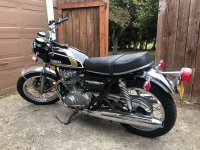
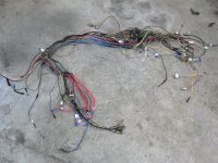
Miss November XS2 tribute

Oh dear! Am sitting on the horns of a dilemma.

Have been looking at the various wiring diagrams in the Haynes manual and factory XS650E manual. I feel the latter should be more or less correct. To make more legible, have been playing with coloured pens again.
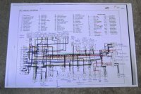

PICT1960.JPG


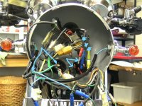
And took a peek at the wiring. Inside the headlamp:
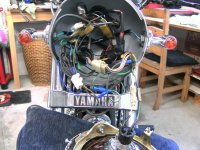

PICT1959.JPG


They sort-of kind-of match, but it's a bit of a mess.

The connectors from the ignition switch have been replaced with socket & jack things, which are a bit loose, hidden by insulating tape which is trying to unwrap itself. No surprise there - that's what insulating tape does.

There's a bunch of five black wires tucked into a domestic wiring block with a blue wire - copper partly exposed - earthed to the indicator mount. The pink horn wire has damaged/missing insulation and some of the others aren't very happy. Lot of blue crimped connectors, which look fairly recent.

Tracing the wires further back will mean delving into the harness and unwrapping it all.

So the question I face is, do I try to understand what is in there, maybe tidy up a few connections? Or do I bite the bullet and re-wire the bike from scratch. Pull it all apart one wire at a time, documenting what comes out, end up with a set of wiring diagrams of my own, like I did a few years back with a Triumph. Then simplify, omit some of the safety relays and rebuild the wiring. But it's a lot of work and at my rate of progress?

Need to sleep on it . . .
 
That's a tough call...on the one hand, you'll know it's done to your standard and all the wires are good with clean connections; On the other hand...it's a TON of work, and may not be necessary. Personally, I would spend a little time cleaning up the wires that need it, tracing the lines and cleaning the connections that are there now--but I wouldn't go too far into the loom (I've found it pretty rare for a wire inside a stock loom to be bad if it's been unmolested...if there's evidence of tampering, burned/shorted, etc within the loom, then that's a different story).

My vote would be to see if you can identify the issue you're having with the ignition (grounding or whatever the problem may be) with what's there...vs. adding potentially other issues into it. If you do that and find the source, then you can still swap the wires out if you want...but at least you'll have the issue resolved. And if you still can't find the source/issue...then perhaps a re-wire is in order...or perhaps it's not the problem and the source lies elsewhere (carbs, etc). That's my thought anyways.
 
Take a fused live direct from the battery to the red lead on the boyer and the live side of the coil, make sure the ground from the boyer is sound, or direct back to neg side of battery. The pickup wires you will have checked. Then start and check. If its OK, Bingo.
 
Yup - I'm with Brassneck and Rasputin. I wouldn't set out to re-wire the bike just yet.

Having said that - IF you decide to do the complete job, MikesXS has very nice wiring harnesses for our bikes at what, in my view, is a very reasonable cost. They also have complete, authentic and good quality handlebar switches (both left and right sides - complete with the wiring pigtails for the switches) for around $69 USD each.

I have used one of these harnesses and both switches and they were all well made, accurate and fitted just fine.

Here is what they offer for your bike in terms of a main wiring harness:
Wire Harness - Main - XS650SE $60.98 IN STOCK Part No. 24-6578
24-6578_main_wiring_harness_1978_xs650e.jpg
 
Thank you all!

Rasputin, I'm, a bit dim on electrics - must be low batt (sorry) - but what you suggest is a method for testing the Boyer box?

Jim, thank you for the colour wiring diagram. For me, part of the value is just trying to get familiar with the diagram. When I first look at a wiring diagram, well, refer back to my answer to Rasputin. But sometimes, by following the diagram, I get the illusion that it's starting to become more familiar & sensible.

The trouble is, I don't feel I understand anything until I understand it all. Today, I will possibly go over the bike along with the wiring diagram identifying the components and maybe even drawing simpler diagrams for one function - power gen, lights, ignition. And of course, some areas have been changed - Boyer instead of points, plus POs will have changed who knows what else.

Hopefully, I might be able to just repair or replace a few dodgy bits like the messy earth in the headlamp shell or the rubbed horn wire. Then, will try to see why it has blown a fuse a couple of times. Have been reading on this forum methods for tracing short circuits - see how that goes.

But if I don't get to a happy place with the wiring, then might decide on total strip out and re-wire. Pete, thank you for the link to new harness from Mike's XS. But if I get to that point, more likely to do it the same way I did the Triumph - buy colour tracer wire and bags of Japanese bullet connectors. I have the wire strippers and crimping tool. Build a simplified wiring system. Because, as said just now, the main thing for me is trying to get to understanding what's in there and how it all fits.
 
Well, after a few hours of contemplating the mess, have reached a few conclusions.

1 Bike electrics are not my thing, but less frit than before I re-wired the Triumph 650.

2 Connectivity within the headlamp shell is, uhm, hit or miss. When I turned the key, there was nothing. But when I just touched the wiring hanging out, the warning lights suddenly came on. Headlamp, tail light, indicators, horn and brake lights all working. But touch the wiring again . . . nothing.

3 The front indicator wiring is appalling. The sky-blue wire from each goes off into harness via a blue crimped connector with bare copper on show. The green wire from each indicator goes NOWHERE and is tucked into the cable insulator - to prevent shorts? See arrowed wire on left of picture.

4 The three wires from the ignition switch - asterisks in picture - are connected through jacks & sockets. Except for the red wire arrowed in the centre, no socket, jack pushed into a blue crimped connector and bare end of wire from harness pushed in from other end.


InkedPICT1961_LI.jpg


So that looks like a prime candidate. I think the red wire to the ignition comes from battery via a fuse and gives power for everything.

But, still wouldn't account for the Boyer playing up when the revs go up?

More work needed as there's probably more faults. But right now, will take the headlamp shell and instruments off for better access and replace the jack with a bullet.
 
But, still wouldn't account for the Boyer playing up when the revs go up?
I think before I went any farther I would get the connections in the headlite bucket repaired. Loose/bad connections can come and go with different frequencies of vibrations. Can be the cause of strange problems.
 
Have been looking at the wiring inside the headlamp shell. Not good. Some wires with missing or damaged insulation, five black (earth) wires with stripped bare copper ends - four were wound together (!) and held in a domestic connector block, one had the bare copper wound round the r/h indicator mounting bolt. The ignition wires already discussed above. One earth wire I traced back along the harness had melted insulation. Took both front indicators off - both had cracked insulation where the wires pass through the hollow mount. And both were so rusty inside the mini-indicator shell I couldn't loosen the screws - now soaking in WD40.

Plus I feel fairly sure the wiring matches neither the layout in the factory manual nor the one Jim very kindly provided.

Think I'm going in.

Strip it all out, record what is there, draw up a wiring diagram, simplify, re-wire it all. Might take weeks but at least it will be a known quantity.

As Mrs might say, will keep me out of trouble for a while.
 
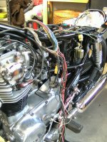
The scene at close of play today:


PICT1966.JPG


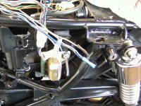
Had been hoping that inside the wiring harness would be undisturbed, then would be able to take it on trust. That was not to be. Close up of a few wires which don't go anywhere:


PICT1962.JPG


PO has capped them off, including some with his favourite blue socket connectors. Then wrapped up in insulating tape. The picture doesn't show the nearby area where three earth wires have been crudely soldered together - there's nothing to prevent shorts apart from the outer tape around the harness.

Oh, well. Finding where little, uhm, shortcuts have been taken at least justifies taking the harness apart.

Feeling a little bit OMG, what have I just done? But if I keep writing down what I find and start drawing pictures of how it all connects, I hope that eventually it will make some sense and might be able to simplify before putting it all back together. I mean, does it need a light checker? Or a flasher cancelling unit? And what is a reserve lighting unit? Plus get rid of safety relays.

There's a site I've used before http://www.vehicle-wiring-products.eu/ which carries a good selection of connectors, tracer cable in all colours, etcetera. Will replace every wire in the main harness. Might be able to re-do some of the peripheral areas as well. Possibly buy new indicators, or see if it's possible to source just the inner bits - bulb holder and so forth.

Might be here for some time . . .
 
As Mrs might say, will keep me out of trouble for a while.
Still following your bike rehab.
Being a red headed Irishman I must admit you seem to have plenty more patience than myself.
Your XS was purchased from a Motorcycle shop right? By now that shop would know me quite well and I wouldn’t be “keeping out of trouble” well at all .
Sorry bout your continued troubles.
-R:cussing:

Machine, thank you for getting angry on my behalf!

Read back over the thread - look at #335 - and you will see that the shop ceased trading before my bike was shipped. After 24 hours of thinking my money had gone 'down the drain' I now feel lucky to have the bike at all but no recourse whatsoever to the seller.

So I have a bike which needs work, more than expected, don't fully match the description, no history, no seller to go back and argue with or demand some money back. But hey, I still think there's a good bike in there. No point getting angry or upset, just have to get on with it.
 
Exactly my point of view Raymond. They’re old, they’re crusty, but they’re ours and once sorted they are great to ride. The journey is half the fun in my opinion.
 
Last edited:
Two things which I never understood or justified before were parting out motorcycles and exporting motorcycles.
Had I the realized the desire and need for nice clean low mileage XS650’s everywhere say, 6 years ago as my own XS650 journey began, exporting local Pacific Northwest USA XS finds sure coulda been spreading some love..
Ah “if wishes were fishes”
Cheers
(Yesterday’s find, local 75)
 

Attachments

  • 14D156DA-05A9-407A-9A21-0CC06194F639.jpeg
    14D156DA-05A9-407A-9A21-0CC06194F639.jpeg
    73.2 KB · Views: 161
I noticed the wiring diagram you've started to color up is for the Standard, the E model. You need the one for the Special, the SE model. They are wired a bit differently because the Standard only has one fuse and the Special has 4. Those loose wires you found not going to anything may be from the reserve lighting unit. I don't see it mounted on the bike (behind the battery) so there's a good chance it has been eliminated. That would create some extra unused wires, and a couple that get jumpered together. Here's a page on removing and bypassing it. As you can see, a couple of the wires need to remain and get connected together for power to flow to the headlight .....

http://www.excess650.co.uk/tips & tricks.htm

And a word on that jumble of ground wires you found in the headlight bucket - no where in the headlight, or anywhere on the front fork for that matter, is considered a good grounding point. The headlight is rubber mounted and the forks connect to the frame through greased bearings. The proper ground is through ground wires coming out of the 2 main harness looms that go into the headlight bucket. These run back and attach to the main frame. There is usually one coming out of each harness loom and it has a multi-bullet connector on the end so several ground wires can be plugged into it. Usually, you'll have one from each turn signal, one from the headlight, one from the instrument lights, and one from the left handlebar control. There's barely enough spots to plug them all in so you may want to provide yourself with a few extras if you're going to be installing multi-plugs yourself. I know I had to add one on my Special for my voltmeter. I actually added another 3-way .....

3ZTwuMd.jpg
 
I noticed the wiring diagram you've started to color up is for the Standard, the E model. You need the one for the Special, the SE model. They are wired a bit differently because the Standard only has one fuse and the Special has 4. Those loose wires you found not going to anything may be from the reserve lighting unit. I don't see it mounted on the bike (behind the battery) so there's a good chance it has been eliminated.

5T, thank you for this - I have been confussed about which wiring diagram applies to my XS.

As you will see from previous posting, things have moved on a bit. I feel the wiring has suffered, both from age and modification. For example, points have been replaced with Boyer ignition. The mini-indicators have been fitted very badly. Don't know what else might have been changed. I'm sure the correct approach would be a new harness as Pete has suggested. But I seem to have got stuck on trying to work out what is in there, given that it has been modded. Then I'll try and put it back together neater, simpler and with my own unique diagram. Even though experience says I'll give myself problems going that way - never seem to learn.

There's few components I haven't been able to identify. Mostly solid-state boxes with wiring which doesn't seem to correspond to anything on the factory diagram - probably because I'm using the wrong diagram. There's a wee box which sits in the tool tray behind the battery with seven inputs - black, black, dark blue, yellow, pale blue/yellow, brown and red/white. Might be light checker, whatever that does, might be reserve lighting, whatever that is.

And some things I've probably wrongly id'd - I've got two wires soldered to the solenoid which at the other end of the bike had down as engine kill. Shurely not . . .

Why can't I do things the easy way?
 
Last edited:
Back
Top